


|
The Pendulum |

|
Clock Circuit
Picaxe 18M2 Programmed with Logicator Flow Chart
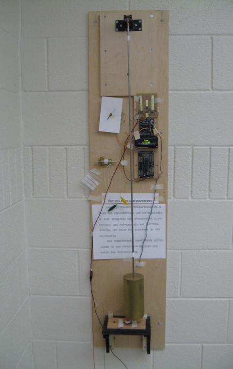
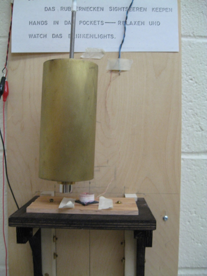
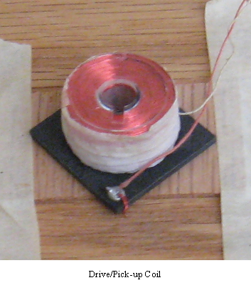
Use the same coil as both a voltage pickup to sense the oncoming magnet, and as an electro-magnet to drive the pendulum. Separation between the pendulum magnet and the coil is about 1 mm.
Magnet: neodymium, chrome plated; cylindrical, ¾”dia. x ½” height with ¼” dia. through hole; centered on pendulum rod below the rating nut. Pickup/Drive coil: the form is a plastic sewing machine bobbin, fully wound with 1480 turns of 34 AWG wire gauge; wire resistance 58.9 Ω; wire length 222 feet.
Read the pickup/drive coil on pin C.1 (actual leg 18) with internal analog/digital converter (ADC). The threshold is set pretty low. If the voltage at C.1 is 5/255 x 5V».1V, then drive the coil; if not, keep checking the input until it is.
This program drives the pendulum at equilibrium each half-period.
Power to drive the bob is adjusted by varying the time during which the output pin C.1 is high, using the “Wait” command.
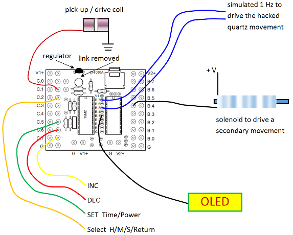
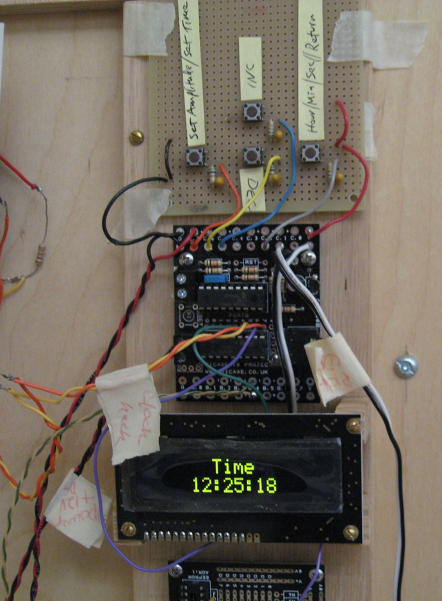
In lieu of a schematic, the circuit layout is shown. Power to the circuit is provided by +12 V dc with an on-board +5 V dc regulator (as shown in the diagram, the link must be removed in order to use the regulator; refer to the PicAxe-18 Project board datasheet for details regarding the power connections). The +5 V is for the 18M2 microprocessor and Darlington transistor chip; the +12 V is used for the solenoid.
The electronics of a small quartz clock movement have been removed so that the going-train of gears, which moves the hands, can be driven by the PicAxe 18M2. These typical quartz movement gear trains require a 1 Hz signal, so the output pins B.5 and B.7 simulate that signal: on one half-cycle, pin B.5 is low and B.7 is high, and on the next half-cycle, the pins’ outputs are reversed. |
|
Output B.4 is connected to the Darlington transistor chip. The output of the Darlington transistor will operate at a higher voltage than the microprocessor and will provide more current than the PicAxe output, and is used to drive a dc solenoid. B.4 is programmed to provide a pulse each second. This solenoid may be used to drive a mechanical movement.
B.3 output displays the time via an OLED (organic light emitting diode) display. Power connections to the OLED are not shown. Momentary contact buttons (set, select Hour/Minute/Second/Return, increment, decrement) are used to control the time display and the power to drive the pendulum.
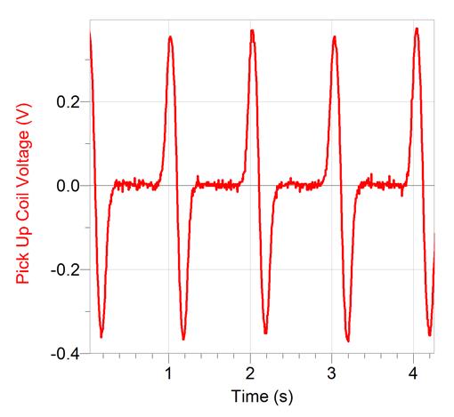
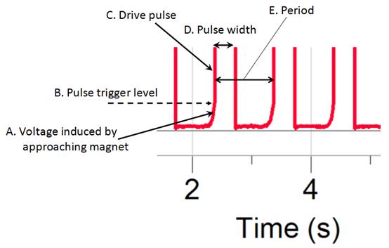
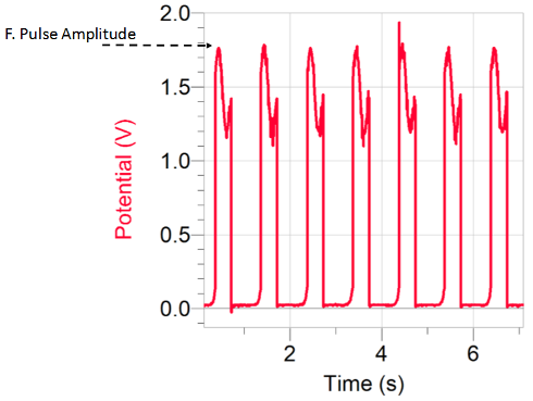
The following graph is the pick-up coil voltage as a function of time as the magnet swings overhead. For this data, the coil is disconnected from the PicAxe microprocessor and therefore the pendulum is not driven. In this graph, zero voltage between pulses occurs when the bob is at maximum amplitude. Notice that as the magnet approaches the coil, the voltage is positive-going. The magnet is at equilibrium, that is, directly over the coil, at the zero crossing between peaks. The coil is connected so that the positive-going voltage occurs first. The microprocessor may be damage or destroyed if the input voltage is negative. The microprocessor is programmed so that as the magnet approaches and is recognized, the pin turns into an output, and a pulse is sent to the coil. This pulse width is variable, but the pin is kept as an output long enough to mask any negative-going voltage at the pin due to the moving magnet.
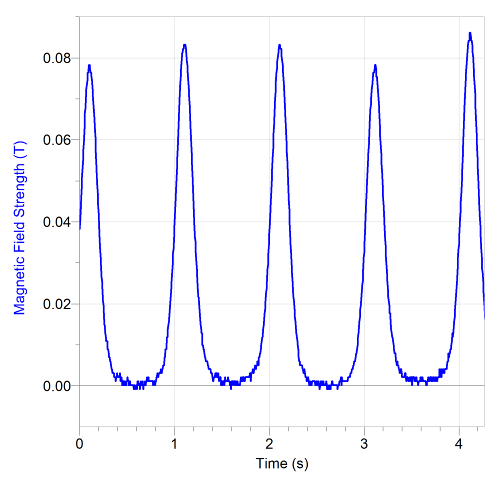
This next graph is a measure of the magnetic field strength of the neodymium magnet. The coil is removed and a Hall sensor is placed under the equilibrium position of the pendulum. The magnet is too strong for the Phillips-Harris Blue-Box magnetic field sensor, so the field is measured – not at the coil location – but about 1.5 cm below the magnet (Recall that the top of the coil is to be placed about 1 mm below the bottom of the magnet.). The magnet is placed under the rating nut such that the South pole is up; therefore, the North pole of the magnet is in closest proximity to the coil, so the orientation of the magnetic field vector is down through the coil.
With a magnetic field perpendicular to the plane of the coil windings, and for a uniformly wound N-turn coil of cross-sectional area A, Faraday’s law gives us the voltage, V, induced in the coil as
The voltage in the coil is proportional to the negative of the rate-of-change of the magnetic field strength through the coil. An inspection of the B vs. t graph below will show that the slope is indeed indicative of the Pick-up Coil Voltage vs. t graph above. The two graphs were made during different experimental runs, of course, so the peak in magnetic field will not necessarily occur at the same time as the zero crossing of the coil voltage.
|
|
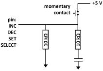
Schematic diagram for the four momentary contact switches.
The 10 kΩ resistor in series and the capacitor to ground are the de-bounce circuit for the switch. The other 10 kΩ resistor is on the 18M2 project board. The voltage at the pin is either +5V (contact) or 0V (open).
Code for reading the switches in Working Pendulum Drive and Clock Program in Basic, given below, has been derived from D. Lincoln’s book “Programming and Customizing the PICAXE Microcontroller”, 2nd edition, Tab Books, 2011. An excellent treatise on PicAxe programming, highly recommended.
|
|
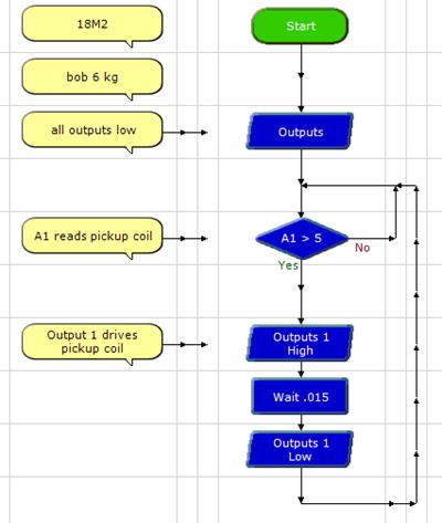
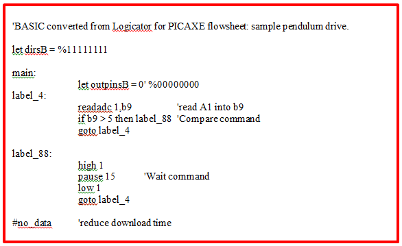
Pendulum Drive Logic
This simple scheme is the basis of the pendulum drive. Upon detection (at pin C.1 via the pick-up coil) of the approaching permanent magnet – attached to the pendulum below the rating nut – the microprocessor converts that input to an output and sends a pulse of variable length to the same coil. The magnetic field produced by this pulse in the coil exerts a force on the permanent magnet, thus driving the pendulum. The pause command determines the length of the pulse delivered to the pendulum. This sample program drives the pendulum every half-cycle but does not drive a clock. |
|
Pick-up/Drive coil voltage
These next two graphs show voltage induced in the coil as the magnet swings nearby. In this case, the coil is attached to the PicAxe microprocessor.
The amplitude of the drive pulse is less than the five-volt output of the PicAxe microprocessor. The maximum current output of the microprocessor is 20 mA, but the coil dc resistance is about 50 Ω. The coil would draw about 100 mA if it were available, but it isn’t, thus the pin voltage is supressed. With 1.75 V, or so, at the pin, the current through the coil is about 35 mA.
The amplitude of the pendulum swing is inversely proportional to the pulse width. |
|
The basic block just after the start command contains the lines:
#picaxe 18M2 pause 500 serout B.3,N2400,(254,1) pause 30
This program illustrates the simulated one Hertz output on pins B.5 and B.7. The variable B indexes the alternate swings of the pendulum. This scheme of hacking a quartz movement and driving it with a simulated 1 Hz is derived from Rod Elliot, http://sound.westhost.com/clocks/index.html
In order to be able to find an average period over 100 half-swings of the pendulum, the variable U is an index to count 100 input pulses in the pick-up coil; the program then sends a pulse out on pin B.6 (the output pulse actually occurs at count 3 and again at count 103). This version of the program does not include any code to read the momentary push-button switches used to set the time or drive pulse delay time. |
|
'BASIC converted from flowchart: 'PicAxe\EOS Laboratory Pendulum\Elliott clock circuit 18M2 version
{ ;Symbols symbol varA = b0 symbol varB = b1 symbol varC = b2 symbol varD = b3 symbol varE = b4 symbol varF = b5 symbol varG = b6 symbol varH = b7 symbol varI = b8 symbol varJ = b9 symbol varK = b10 symbol varL = b11 symbol varM = b12 symbol varN = b13 symbol varO = b14 symbol varP = b15 symbol varQ = b16 symbol varR = b17 symbol varS = b18 symbol varT = b19 symbol varU = b20 symbol varV = b21 symbol varTEMPBYTE1 = b22 symbol varTEMPBYTE2 = b23 symbol varTEMPBYTE3 = b24 symbol varTEMPBYTE4 = b25 symbol varTEMPBYTE5 = b26 symbol varTEMPBYTE6 = b27 symbol varTEMPWORD1 = w11 symbol varTEMPWORD2 = w12 symbol varTEMPWORD3 = w13 }
main: let dirsB = 0 let dirsC = 8
#picaxe 18M2 pause 500 serout B.3,N2400,(254,1) pause 30 let varD = 51 let varH = 10 let varC = 0 let varB = 0 low B.0, B.1, B.2, B.3, B.4, B.5, B.6, B.7
Cell_7_5: readadc C.1, varTEMPBYTE1 if varTEMPBYTE1 >= 0 and varTEMPBYTE1 <= 5 then goto Cell_7_5 end if if varB = 1 then goto Cell_7_8 end if high B.5, C.1
pause 350 low B.5, C.1
pause 100 let varB = 1 Cell_13_15: if varC = 59 then goto Cell_16_15 end if let varC = varC + 1 Cell_13_8: serout B.3, N2400, (254,128," Time ") bintoascii varC, b11, b12, b13 bintoascii varD,b14,b15,b16 bintoascii varH, b17,b18,b19 if varH > 9 then goto line200 serout B.3, N2400, (254,192, " ",b19,":",b15,b16,":",b12,b13," ") goto line400 line200: serout B.3, N2400, (254,192, " 1",b19,":",b15,b16,":",b12,b13," ") line400: if varU = 3 then goto Cell_16_7 end if Cell_13_5: inc varU if varU = 103 then goto Cell_16_4 end if goto Cell_7_5
Cell_16_4: let varTEMPWORD1 = 10 pulsout B.6, varTEMPWORD1 let varU = 0 goto Cell_7_5
Cell_16_7: let varTEMPWORD1 = 10 pulsout B.6, varTEMPWORD1 goto Cell_13_5
Cell_16_15: let varC = 0 let varD = varD + 1 if varD = 60 then goto Cell_16_12 end if goto Cell_13_8
Cell_16_12: let varD = 0 let varH = varH + 1 if varH > 12 then goto Cell_16_9 end if goto Cell_13_8
Cell_16_9: let varH = 1 goto Cell_13_8
Cell_7_8: high B.7, C.1
pause 350 low B.7, C.1
pause 100 let varB = 0 goto Cell_13_15
#no_data 'reduce download time
//////////////////////////////////////////////////////////////////////////////////////////////////////////////////////////////////////////////////////////////////////////////////////////////////////////////////////
This is the program currently in use:
Working Pendulum Drive and Clock Program in Basic
'BASIC converted from flowchart: #picaxe 18M2
{ ;Symbols symbol varA = b0 symbol varB = b1 'path index, 1 or 2; needed only for hacked quartz movement symbol varC = b2 'counter; up to 100 symbol delay = b3 'delay after driving pendulum symbol varE = b4 'char1 for hour symbol varF = b5 'char2 for hour symbol varG = b6 'char3 for hour symbol H = b7 'hour symbol varI = b8 symbol varJ = b9 'char1 for min symbol varK = b10 'char2 for min symbol varL = b11 'char3 for min symbol M = b12 'minute symbol bcdnum = b13 'bcdnum (varN) symbol bcdmin = b14 'bcdmin (varO) symbol bcdmax = b15 'bcdmax (varP) symbol varQ = b16 symbol varR = b17 symbol S = b18 'seconds symbol varT = b19 'char1 seconds symbol varU = b20 'char2 seconds symbol varV = b21 'char3 seconds symbol coil = b22 'coil symbol varTEMPBYTE2 = b23 'char1 amplitude symbol varTEMPBYTE3 = b24 'char2 amplitude symbol varTEMPBYTE4 = b25 'char3 amplitude symbol varTEMPBYTE5 = b26 symbol varTEMPBYTE6 = b27 symbol varTEMPWORD1 = w11 symbol varTEMPWORD2 = w12 symbol amplitude = w13 'amplitude = length of pulse to drive pendulum = pause length for pulse; 100ms to 500ms } main: let dirsB = 0 let dirsC = 8
symbol down = 1 symbol up = 0
symbol setampbutton = pinC.7 symbol settimebutton = pinC.2 symbol incbutton = pinC.5 symbol decbutton = pinC.6
pause 500 serout B.3,N2400,(254,1) pause 30
let amplitude = 350 let delay = 100
let M = 59 let H = 12 let S = 0 let varB = 0 'index for path, either 0 or 1 let varC = 0 'index counter for 100 seconds (50 complete swings) 'main loop do gosub drivependulum setint %10000000,%10000000 'activate interrupt when pin7 goes high 'first number = high(or low), second number = pin7 (only) 'disables itself after use, so it must be put in loop loop
interrupt:
gosub setamplitude gosub settime
return
'subroutines drivependulum:
Cell_7_5: readadc C.1, coil 'C.1 is the coil if coil >= 0 and coil <= 5 then goto Cell_7_5 end if if varB = 1 then goto Cell_7_8 end if high B.5, C.1, B.4
pause amplitude low B.5, C.1, B.4
pause delay let varB = 1 Cell_13_20: If S = 59 then goto Cell_16_20 end if let S = S + 1 Cell_13_11: serout B.3, N2400, (254,128," Time ") bintoascii S, b19, b20, b21 bintoascii M,b9,b10,b11 bintoascii H, b4,b5,b6 if H > 9 then goto line200 serout B.3, N2400, (254,192, " ",b6,":",b10,b11,":",b20,b21," ") goto line250 line200: serout B.3, N2400, (254,192, " 1",b6,":",b10,b11,":",b20,b21," ")
line250: 'count from 3 (start) to 103 (100 pulses later) and send pulses (output B.6) to 28X2 chip; '100 half-swings between pulses; should be 100 seconds
If varC = 3 then goto line168 end if line136: inc varC if varC = 103 then goto line164 end if goto line600
line164: pulsout B.6, 1000 let varC = 0 goto line600
line168: pulsout B.6, 1000 goto line136
Cell_16_20: let S = 0 let M = M + 1 If M = 60 then goto Cell_19_16 end if goto Cell_13_11
Cell_19_16: let M = 0 let H = H + 1 if H > 12 then goto Cell_19_12 end if goto Cell_13_11
Cell_19_12: let H = 1 goto Cell_13_11
Cell_7_8: high B.7, C.1, B.4
pause amplitude low B.7, C.1, B.4
pause delay let varB = 0 goto Cell_13_20 line600: return
setamplitude: do while setampbutton = down loop bcdmax = $32 : bcdmin = $0A 'limits 50 max, 10 min; arbitrary scale 100 to 500 do serout B.3, N2400, (254,128," Set Amplitude ") bintoascii amplitude, b23, b24, b25 serout B.3, N2400, (254, 192, " ",b23,b24,b25," ")
if incbutton = down then bcdnum = amplitude/10 gosub bcdinc amplitude = bcdnum*10 bintoascii amplitude, b23, b24, b25 serout B.3, N2400, (254, 192, " ",b23,b24,b25," ") do while incbutton = down loop endif
if decbutton = down then bcdnum = amplitude/10 gosub bcddec amplitude = bcdnum*10 bintoascii amplitude, b23, b24, b25 serout B.3, N2400, (254, 192, " ",b23,b24,b25," ") do while decbutton = down loop endif if setampbutton = down then goto line300 loop line300: return
settime: do while settimebutton = down loop serout B.3, N2400, (254,128,"Set Time: Hour") serout B.3, N2400, (254,192, " ",b5,b6,":",b10,b11,":",b20,b21," ") bcdmax = $0C : bcdmin = $01 do bcdnum = H if incbutton = down then do while settimebutton = down loop gosub bcdinc H = bcdnum bintoascii H, b4,b5,b6 serout B.3, N2400, (254,192, " ",b5,b6,":",b10,b11,":",b20,b21," ") do while incbutton = down loop endif if decbutton = down then do while settimebutton = down loop gosub bcddec H = bcdnum Bintoascii H, b4,b5,b6 serout B.3, N2400, (254,192, " ",b5,b6,":",b10,b11,":",b20,b21," ") do while decbutton = down loop endif if settimebutton = down then goto line500 loop
line500: do while settimebutton = down loop serout B.3, N2400, (254,128,"Set Time: Minute")
bcdmax = $3B : bcdmin = $01 do bcdnum = M if incbutton = down then do while settimebutton = down loop gosub bcdinc M = bcdnum bintoascii M, b9,b10,b11 serout B.3, N2400, (254,192, " ",b5,b6,":",b10,b11,":",b20,b21," ") do while incbutton = down loop endif if decbutton = down then do while settimebutton = down loop gosub bcddec M = bcdnum bintoascii M, b9,b10,b11 serout B.3, N2400, (254,192, " ",b5,b6,":",b10,b11,":",b20,b21," ") do while bdecbutton = down loop endif if settimebutton = down then goto line700 loop
line700: do while settimebutton = down loop serout B.3, N2400, (254,128,"Set Time: Second")
bcdmax = $3B : bcdmin = $01 do bcdnum = S if incbutton = down then do while settimebutton = down loop gosub bcdinc S = bcdnum bintoascii S, b19,b20,b21 serout B.3, N2400, (254,192, " ",b5,b6,":",b10,b11,":",b20,b21," ") do while incbutton = down loop endif if decbutton = down then do while settimebutton = down loop gosub bcddec S = bcdnum bintoascii S, b19,b20,b21 serout B.3, N2400, (254,192, " ",b5,b6,":",b10,b11,":",b20,b21," ") do while decbutton = down loop endif
if settimebutton = down then goto line900 loop line900: return
bcdinc: bcdnum = bcdnum + 1 if bcdnum > bcdmax then bcdnum = bcdmin endif return
bcddec: if bcdnum = bcdmin then bcdnum = bcdmax else bcdnum = bcdnum - 1 endif return
#no_data 'reduce download time |

|
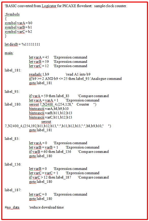
Slightly more complex version of a clock counter.
This version incorporates the clock counter with the drive code. |
|
finito |

|
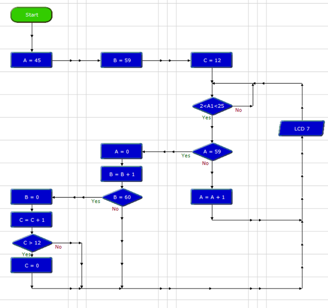
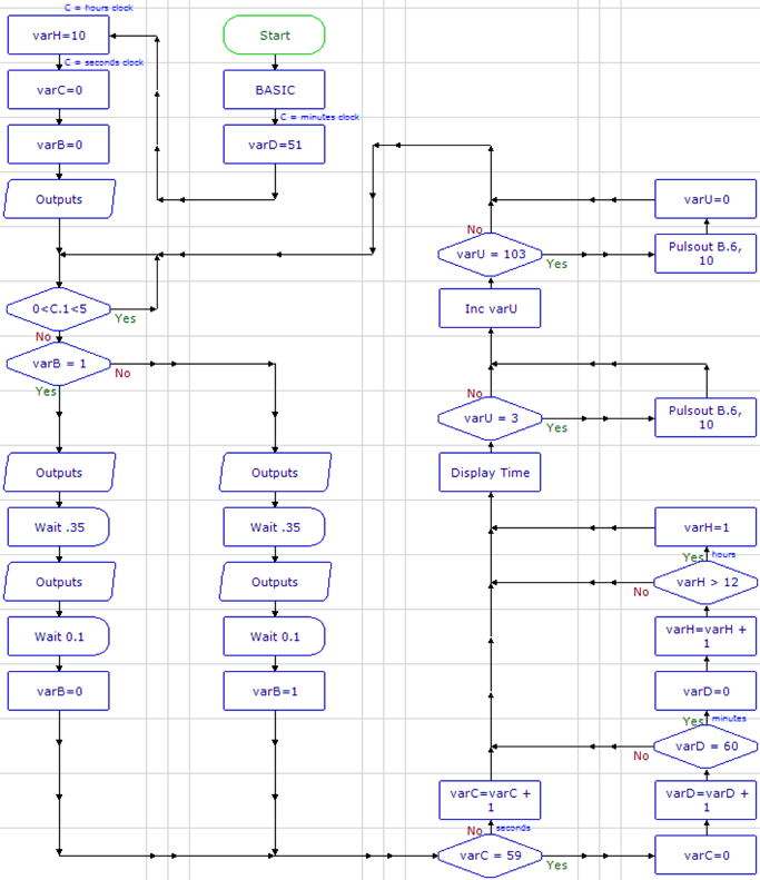
Clock Counter Logic
A scheme for a clock counter using Picaxe 18M2 for a two second period pendulum, which counts every half-period.
In this example, A represents seconds, B represents minutes, and C represents hours. Entering initial values is the only way to set the clock in this test version of the counter.
First, set the analog sensor range. The Analog command reads the voltage at the pin connected to the pickup coil; this command is also a logic test. Here, the range is set between about 2/255 x 5V = 40mV and 500mV. The voltage becomes within this range as the magnet approaches equilibrium; the counter advances by one.
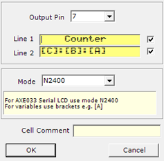
The LCD (liquid crystal display) command displays the time via pin B.7 (actual leg 13); in this instance, the default setting displays three digits without suppressing the zeros before a number. To suppress the zeros, the code must be modified by hand in Basic language. |