


|
The Pendulum by Shelby Cain and M Nealon |

|
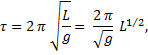
An idealized pendulum oscillates over small amplitudes only and consists of a bob attached to a massless rod. The rod constrains the bob to move along a circular arc. Confining the motion of the pendulum to small amplitudes allows for a simple expression for the period, τ; namely,
Length is measured from the rod’s pivot point to the center-of-mass of the bob regardless of the size or shape of the bob, or method of suspension. The acceleration due to gravity at the earth’s surface, g, varies with location because the earth is an oblate spheroid of non-uniform density. Here, we take g to be 9.80665 m/s2, but neither the number of significant figures nor the exact value are important as long as the value does not change wherever the pendulum happens to be.
Thus, for a two-second period, length = g/π2 = .993621 meters. A two-second period is quite convenient for clock making since the clock would advance one second for each half-swing of the pendulum. This arrangement may decrease the complexity of the timing chain of gears driving a mechanical secondary movement – if one is used.
Notice that of all parameters that might describe a pendulum, the period depends on length alone. If the pendulum regulates a clock then the time rate can be adjusted by a simple adjustment of the pendulum’s length.
The accuracy of a pendulum clock is highly dependent on the exact adjustment of the length simply because there are a lot of seconds in a day. Suppose the length was misadjusted – too short, say, by 0.1 millimeter (about four thousandths of an inch); that is, suppose the length was 0.993521 meters. If this were the case, the pendulum would have a period of 1.99990 seconds.
As there are 86,400 seconds in one day, this pendulum would oscillate
A properly adjusted two-second pendulum oscillates 43,200 times in one day, so this improperly adjusted pendulum has two extra oscillations. Two extra oscillations per day means the clock ticks four extra times per day, or an error of 4 seconds per day “fast”. Four seconds per day is about the same as 2 minutes per month, or about 24 minutes per year. This might not be acceptable for a clock. However, measuring the pendulum length this precisely would be difficult even with precision measuring instruments such as calipers or micrometers. |


|
In a practical sense, a clock’s time rate is not set by the direct measure of the pendulum length. The length is adjusted as precisely as possible and the rate is determined by watching the clock over an extended time. The rate is then compared with some outside reference such as radio station WWV operated by the National Institute of Standards and Technology (the old National Bureau of Standards). The length is then readjusted as necessary.
A real pendulum deviates from the ideal in a number of ways, some of which may be compensated for, some may not. For example, with a spring steel suspension the precise location of the pivot point may not be fixed in place; that is, the effective point about which the pendulum rotates may shift downward slightly as the spring flexes, thus in essence altering the length of the pendulum. This inability to account for all aspects of the real pendulum means that these calculations should be taken only as a guideline in the design of a pendulum.
For a practical clock, considerations such as the rod length and its material, the mounting brackets, the size of the cabinet, the gear ratios of a secondary movement, the driving mechanisms for both the pendulum and the secondary, the spring suspension, the bob design, the energy lost in deflecting the air molecules, any changes in humidity, atmospheric pressure and temperature, etc., ought to be taken into account before construction begins.
The pendulum must be driven in such a manner that any energy loss due to friction at the pivot, and due to air resistance would be overcome exactly by the driving force; if so, a constant amplitude results. In other words, the pendulum must be driven at a constant rate over a long time compared to the period. Furthermore, since the period (of the ideal) is determined by the distance from the pivot point to the center-of-mass, the length must be constant.
For circular-arc motion, the period is not isochronous but presumed so for the derivation. The period of a pendulum moving in a circular arc depends, however slightly, on the amplitude – in other words, a larger amplitude has a longer period; this is a second-order effect and is called “circular error”. A proper isochronous pendulum would follow a cycloidal-arc. A pendulum with circular-arc over a small amplitude is a good approximation of isochronous motion, and, in addition, is easier to make than a cycloid. It is true, of course, that a pendulum with circular error, however large, may be used equally well as a timekeeper – as long as the amplitude is held constant.
The EOS Physics Laboratory Pendulum
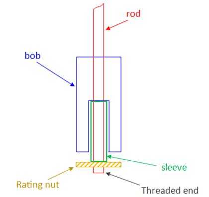
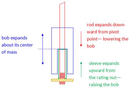
In considering a real pendulum, the length will vary if the rod expands or contracts with changes in temperature. A few standard techniques have been developed over the years to counter the problem associated with thermal expansion. This problem may be lessened by using a rod with a low expansion coefficient; however, these rods may have substantial mass and perhaps cannot be approximated as massless. Likewise, since the bob itself will expand or contract with temperature changes, a slight change in the effective length of the pendulum may occur. One old technique is the use of glass vials of mercury as the bob. These vials are suspended at their lower end so that the liquid mercury expands upward in the vial; this compensates for the downward expansion of the rod. Mercury is selected because it has a relatively high thermal expansion coefficient. Another technique, used here, is to suspend the bob at its center-of-mass. In this manner, the bob’s expansion or contraction about its center-of-mass has no effect on the period. This is illustrated in the figure below. |
|
Support of bob at its center-of-mass, in cross-section view. The rating nut is used to adjust the position of the bob and thus the length of the pendulum system. The bob is supported at its center of mass by a sleeve over the rod. First, the sleeve length is calculated to counter the thermal expansion of the rod; the total bob height is then designed to be just shorter than twice the length of the sleeve. The sleeve sits on the rating nut. Note that in order that the threads engage the rating nut, and to allow for a little leeway in making the adjustment, the rod must extend a small distance beyond the sleeve. ____________________________
The bob is a cylindrical brass can, 6.06” high x 3.00” diameter, filled with lead shot and with end caps fully soldered on. Its mass is 5.9665 kg. The central tube, through which the rod passes, is constructed with three parts, also in brass: in the bottom-half of the bob, which accommodates the sleeve, the central tube has a 13/32” inside diameter; the upper-half tube has a ¼” inside diameter. The two tubes are joined together by a small shelf, or platform – the bottom of which rests on the sleeve. The sleeve used in these experiments, 3.17” long x 9/32” outside diameter, is brass, although the bob is designed for a copper or stainless steel sleeve.
The rod is Invar steel, ¼” diameter. |
|
Pendulum mount
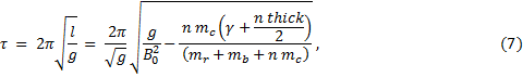
The spring steel used as a pivot is ½” x 1” x 0.005” and is supported at the top by a brass machine screw which passes through a hole in the steel spring. Knurled nuts act as clamps. A flat brass piece in the shape of a “T” is silver-soldered into a slot in the top of the Invar rod. This “T” engages into a copper hook (attached by #4-40 machine screw) at the bottom end of the spring in such a manner to allow for a quick disconnect of the rod without screw fasteners or other clamps.
Center-of-mass
Pendulum rods are not really massless so we may wish to include the mass of the rod as part of a “pendulum system”. The rod’s mass has the effect of shifting the system’s center-of-mass upward in comparison to an ideal massless rod of the same length. The position of the bob must therefore be shifted somewhat, compared to the ideal, in order that this real pendulum have the desired period.
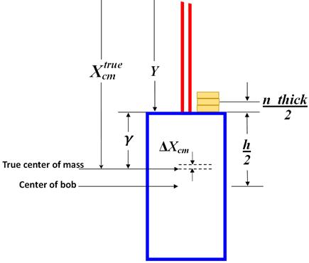
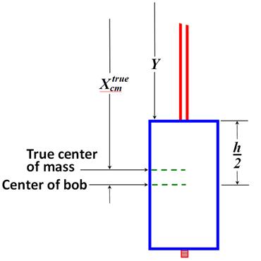
For a two-second pendulum, the center-of-mass of the system must be 0.993621 meters. Let us call this length Xtruecm. The purpose here is to calculate the position of the center-of-mass of the system, as illustrated in the figure below. The origin of our one-dimensional coordinate system is the pivot point. For two objects, in this case the bob and the Invar rod, the position of the center-of-mass is
where xr is the distance from the pivot point to the center-of-mass of the Invar rod, xb is the distance from the pivot point to the center-of-mass of the bob, mr is the mass of the Invar rod, mb is the mass of the bob.
The distance, Y, from the pivot point to the top of the bob is measured with an ordinary meter stick. Once this distance is determined, the length is not adjusted further during these experiments. We find
|
|
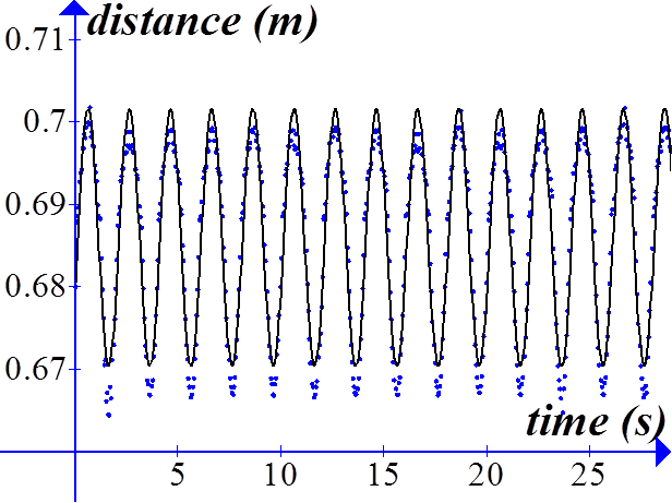
Sonic detector data from Logger-Pro software by Vernier.
A sonic motion detector and curve fitting software have been used to determine the period. This is a typical run with no coins on the bob. Although only 30 seconds of data are shown here, the length of all data runs was 60 seconds; the rate at which data was taken was 20 samples/second; the best-fit sine function is in black and the data is in blue. The amplitude is not such a great fit, but the period is
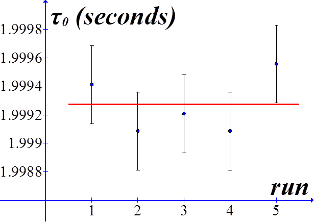
Period data taken about one week apart. Shown in red is the mean τ value, 1.9992702 seconds. Typical RMS error bars are given, calculated by the Logger Pro best-fit sine function to sonic detector data.
Include the Small Parts
At this point it might be interesting to include in the true center-of-mass calculation, all the constituent parts of the pendulum just to see whether we are justified in excluding them. The most massive among these small parts are the magnet and rating nut. The mass of these parts have the effect of increasing the effective length of the pendulum. With the small parts, then, the center-of-mass measured from the pivot point is
xr = 0.5602 m xb =1.0015 m xspring = 0.00127 m xnut =1.0852 m xmagnet = 1.1336 m xsleeve =1.0416 m xspringclamp = 0.00254m mb = 5.966 kg mr = 0.223 kg mspring = 0.00042 kg (average of several springs) mnut = 0.02262 kg mmagnet = 0.02425 kg msleeve = 0.00715 kg mspringclamp = 0.00357 kg.
Consequently,
Inclusion of these small parts changes the value of the effective length of the pendulum by an amount about one-half millimeter. |
|
One-dimensional thermal expansion of a rod of length L0 may be described by the empirical formula
where, ΔL is the change in length, α is the thermal expansion coefficient, and, ΔT is the change in temperature. The rod and sleeve are to expand an equal amount for a given temperature change, so we can write
Let us pick a material,say, copper, for the sleeve and calculate the length required. To calculate the sleeve length we need the length of the rod from the pivot point to the rating nut. The distance to the center of mass of the pendulum system is very close to one meter exactly; to this we must add half the height of the bob. This total length is 1.085 meters. Therefore,
Thus, the bob is 6.1” in height. |
|
Rating Nut Adjustment
If one were to pitch the end of the rod at, say, 40 threads per inch – which is the finest die readily (well, imported from England, if you call that readily) available for a ¼” rod – then each complete turn the rating nut will change the pendulum length an amount 1/40th of an inch (= .025” = 0.635 millimeters). The rate-of-change of period with respect to length is given by dτ/dL, where here we have used the upper case L for the length of a pendulum in the general case. Since
the derivative is
or,
where we have written the change in period in terms of τ. Then for a two-second period we have
If we take dL = 6.35x10⁻⁴ m for one complete turn (at 40 threads per inch), and g = 9.80665 m/s2, then one rotation of the nut will change the period by an amount
Suppose, for this two-second period pendulum, that the rating nut was turned once around to raise the bob. The new period would be 2. – (6.39077 x 10⁻⁴) seconds. The pendulum would oscillate
leading to an error of 14 oscillations per day, or 28 seconds per day, or about 14 minutes per month – quite a large error. One-twelfth of a turn (the same angle as 5 minutes on a 12-hour clock) would cause an error of about 2 seconds per day (or about 14 minutes per year). This means that the threads ought to have a finer pitch and that the pendulum needs be stable enough so that any adjustment required of the nut would be much less than one complete turn. |

|
Thermal expansion
If the pendulum bob is mounted as described above, then the thermal expansion of the rod is countered by the thermal expansion of the sleeve. As, for example, the temperature of the pendulum increases, the rod would expand, lowering the bob. Since the rod is suspended at its top end, very nearly the full length of the rod comes into play with thermal expansion. The length referred to here is the distance from the pivot point to the rating nut – any expansion of the rod below the nut plays no part in changing the period. The sleeve, however, expands upwards raising the rod. A judicious choice of expansion coefficients allows the two expansions to counter each other exactly and therefore alleviate any temperature effects on the pendulum. The bob itself is suspended from its center-of-mass so it expands above and below that point without effect on the period. This idea is illustrated in the figure.
The rod is made of Invar-36, a particular nickel-steel alloy designed for low thermal expansion applications such as pendulum rods. Fused quartz has a lower coefficient and has about the same cost as Invar, but would require epoxy or some other method to attach the fittings; furthermore, its breakability may be troublesome, so at present Invar is the best choice.
Generally, pendulum bobs are made of brass or lead, both of which have relatively high expansion coefficients. Melted lead might be poured into a brass container, or “can”; or, perhaps the bob might be a brass can of lead shot. If the latter is the case, then the density of the bob will be less than solid lead (or perhaps even less than solid brass) because of the voids between shot pellets; however, any thermal expansion will still be about the center-of-mass of the bob – if suspended in the manner described above.
Also, we see from the figure that the bob is not exactly symmetric about its center-of-mass because of the void left for the sleeve in the bottom-half is larger than the void for the rod in the top-half. This mass difference is insignificantly small compared to the overall mass of the bob; however, an asymmetric bob could be constructed to compensate for this slight difference.
Table of expansion coefficients of selected materials: |
|
Addition of coins to the top of the bob in a single stack
We may tire of trying to regulate the period of the pendulum by raising or lowering the bob – if, for example, the threads are not fine enough – we might try dropping a few coins on top of the bob. This is a technique used effectively on the pendulum of the great clock in the tower at the Houses of Parliament in London. That four-second period pendulum is subject to all manner of environmental conditions which can alter the period. A single pre-decimal British pence coin placed on the shoulder of the bob’s mounting bracket (about one meter above the system center-of-mass) purportedly will alter the period by two-fifths of a second in 24 hours.
The equation for the period of an ideal pendulum does not include any variable for mass; this means that the mass of the bob does not determine the period of the pendulum. Adding mass in the form of coins to the top of the bob has the effect of shifting the location of its center-of-mass, and thus the length of the pendulum, and therefore its period. Let us see how effective this technique is in regulating the time rate of the clock. A maximum of twelve like-denomination coins are used in these experiments.
First of all, the center-of-mass of the bob is raised by adding coins to the top, not lowered; this increases the time rate, so in order for this method of regulation to be effective, the time rate must already be “slow”.
Before the addition of any coins to the system, we have
where γ is the distance from the true center-of-mass to the top of the bob. Solve for γ, and substitute in equation (3’), the true center-of-mass, which includes the small parts.
Let n be the number of coins, each of thickness thick, stacked on top of the bob. The center of this stack of n coins is a distance
above the top of the bob. The magnitude, then, of the change-in-position of the center-of-mass, ΔXcm, relative to the true center-of-mass, is
where mc is the mass of a single coin. In the denominator is an expression for the total mass; here we ignore the smaller constituent parts of the pendulum. Recall that in general the period of a pendulum is given by
and that the period may be determined by experiment from the sonic detector parameter, B, which is the angular frequency of the sine function fit to the detector data. We have
and
Now that the bob is heavily laden with coins, the effective length of the pendulum, l, is
where L0 = g/B02. The period as a function of n, then, is
where the initial length, L0, i. e., the length with no coins present, has been written in terms of the sonic detector data rather the length measurements. |


|
Rate-of-Change of Period
We are interested in the rate-of-change of the period with respect to the number of coins. Using the chain rule we may write
The first factor on the right-hand side is the derivative of τ with respect to length. We have seen this derivative earlier, and we now substitute in the expression for the effective length of the pendulum after the addition of coins,
In order to understand how the theoretical expression for the rate-of-change of the period may be compared to experiment, let us derive three expressions for dτ/dn. Two of our expressions are approximations; one is an exact derivative. |

|
Theory 1. Approximating the differential length, dl.
Approximate the differential, dl, with the change in position of the center-of-mass due to the addition of coins; namely, let
Recall that ΔXcm is the magnitude of the shift of the center-of-mass. We now have
so,
Notice that the differential, dn, is equal to one; coins are quantized, so to speak. A plot of dτ vs. n should give a linear, or nearly linear, result. We may write
The function dτ/dn as written here is not exactly linear in n, but nearly so.
Data and Theory
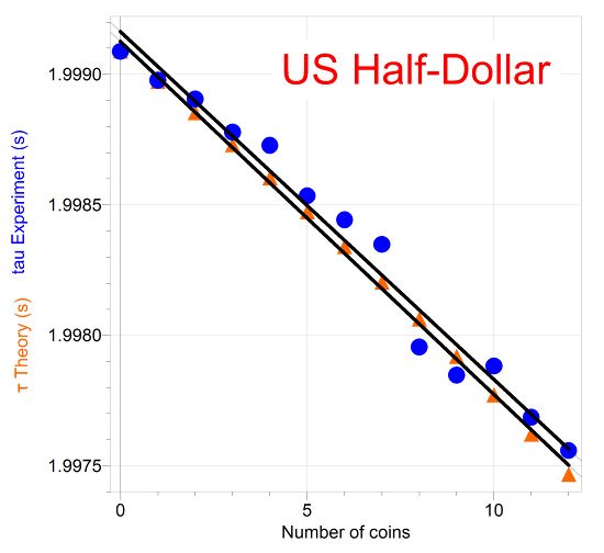
Sine curve fits to sonic detector data give the angular frequency, B. The period is determined from the angular frequency and is plotted in blue dots against the number of coins. The theory which predicts τ, equation (7), is also plotted – in orange triangles.
The slope of the experimental period vs n graph for US half-dollars is -1.33x10⁻⁴ seconds/coin, and the slope of the theory is -1.35x10⁻⁴ seconds/coin. |

|
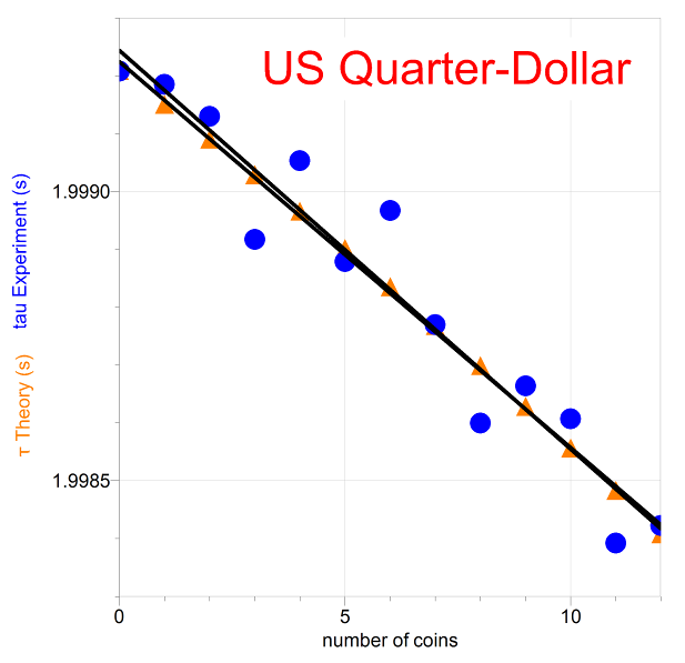
The slope of the experimental period vs n graph for US quarters is -6.89x10⁻⁴ seconds/coin, and the slope of the theory is -6.67x10⁻⁴ seconds/coin. |
|
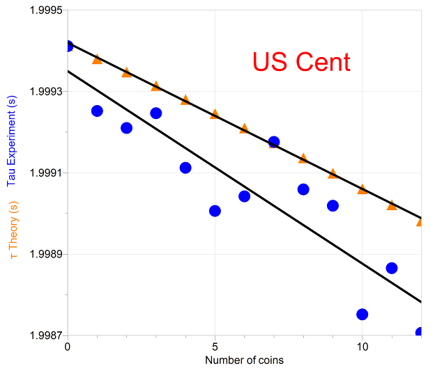
The slope of the experimental period vs n graph for US pennies is -4.73x10⁻⁵ seconds/coin, and the slope of the theory is -3.59x10⁻⁵ seconds/coin, about a 30% difference. |
|
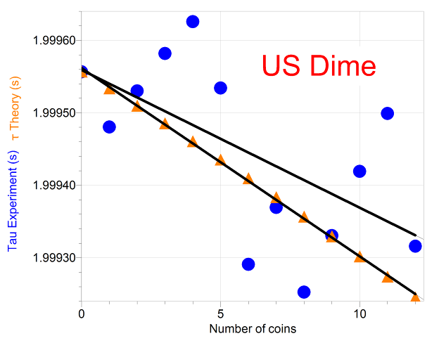
The slope of the experimental period vs n graph for US dimes is -1.90x10⁻⁵ seconds/coin, and the slope of the theory is -2.60x10⁻⁵ seconds/coin, more than a dime’s worth of difference (well, really a bit less than about 30%). |


|
The top end of the Invar rod is below the pivot point by an amount equal to the length of the spring. With a uniform density, the rod’s center of mass is the physical center, so
Let h be the height of the bob. The distance to the center of the bob is Y plus half the height of the bob. For h = 0.155 m, we have
The masses are measured on laboratory balances. We find
and,
Therefore,
|
|
Y |
0.9240 m |
|
xr |
0.5602 m |
|
xb |
1.0015 m |
|
mr |
5.966 kg |
|
mb |
0.223 kg |
|
lrod |
1.0696 m |
|
lspring |
.0254 m |
|
h |
0.155 m |
|
Y |
0.9240 m |
|
xr |
0.5602 m |
|
xb |
1.0015 m |
|
mr |
0.223 kg |
|
mb |
5.966 kg |
|
xspring |
0.00127 m |
|
xnut |
1.0852 m |
|
xmagnet |
1.1336 m |
|
xsleeve |
1.0416 m |
|
xspringclamp |
0.00254 m |
|
mspring |
0.00043 kg |
|
mnut |
0.02262 kg |
|
mmagnet |
0.02425 kg |
|
msleeve |
0.00715 kg |
|
mspringclamp |
0.00357 kg |
|
use: |
material |
α (x 10-6 1/C) |
|
sleeve |
Steel |
11 |
|
Stainless Steel 314 alloy |
15 |
|
|
Stainless Steel 316 alloy |
16 |
|
|
Copper |
16.5 |
|
|
Brass |
19 |
|
|
Aluminum |
23 |
|
|
rod |
Invar-36 |
1.22 |
|
Fused quartz |
0.5 |
|
|
bob |
Lead |
29 |
|
Mercury |
18 |