
|
EOS |
|
Instruments |

|
Rate Sensor |
|
Programming Exercise in PicAxe |
|
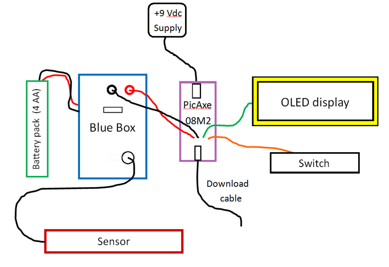
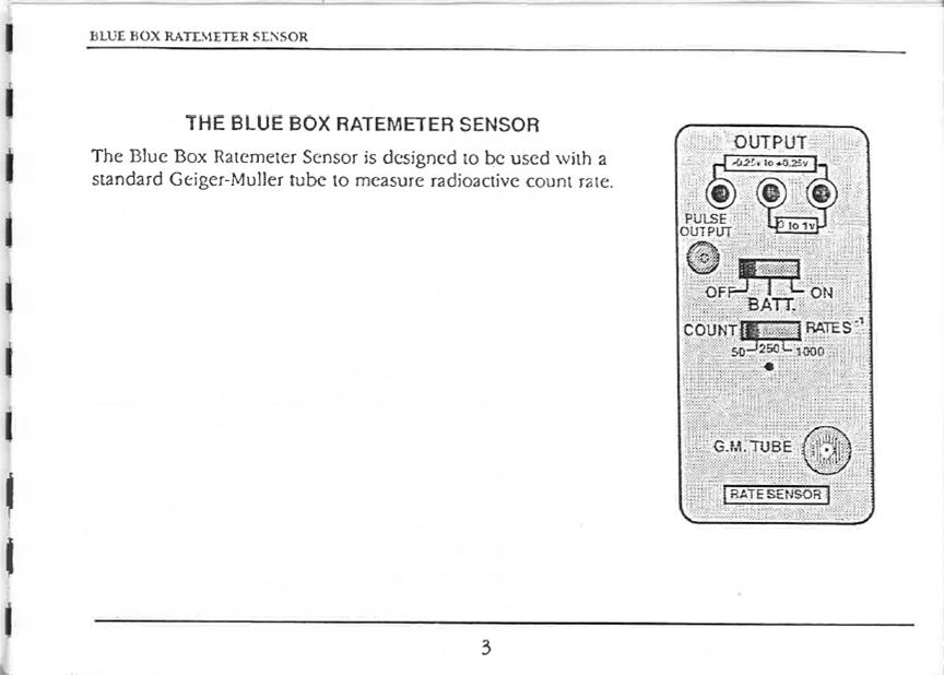
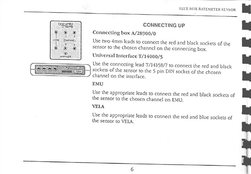
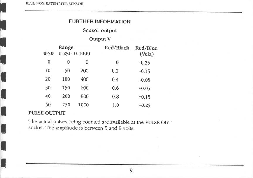
The output of the Philip Harris Rate Sensor is directly proportional to the number of radioactive events per second detected by the Geiger-Müller tube. The Blue Box output voltage ranges from 0 to +1V. Count rates are measured in events, or counts, per second (1/s) on three scales, switch-selected: 10 counts per second, 250 counts per second and 1000 counts per second. |
|
Power Supply on PicAxe Circuit Board Power Input: +7.0 V to +35.0V; connector is center positive; nominally +9.0V dc power adaptor is used (+9.0 V battery for portable use, but avoid if possible since current drain is high - battery won’t last long). Power Output: +5.0 V, regulated 200mA maximum current Red LED “on” indicator. This power supply is hardwired to both the PicAxe and the OLED display; red lead positive/black lead ground, 0V. |
|
Blue Box Manual |
|
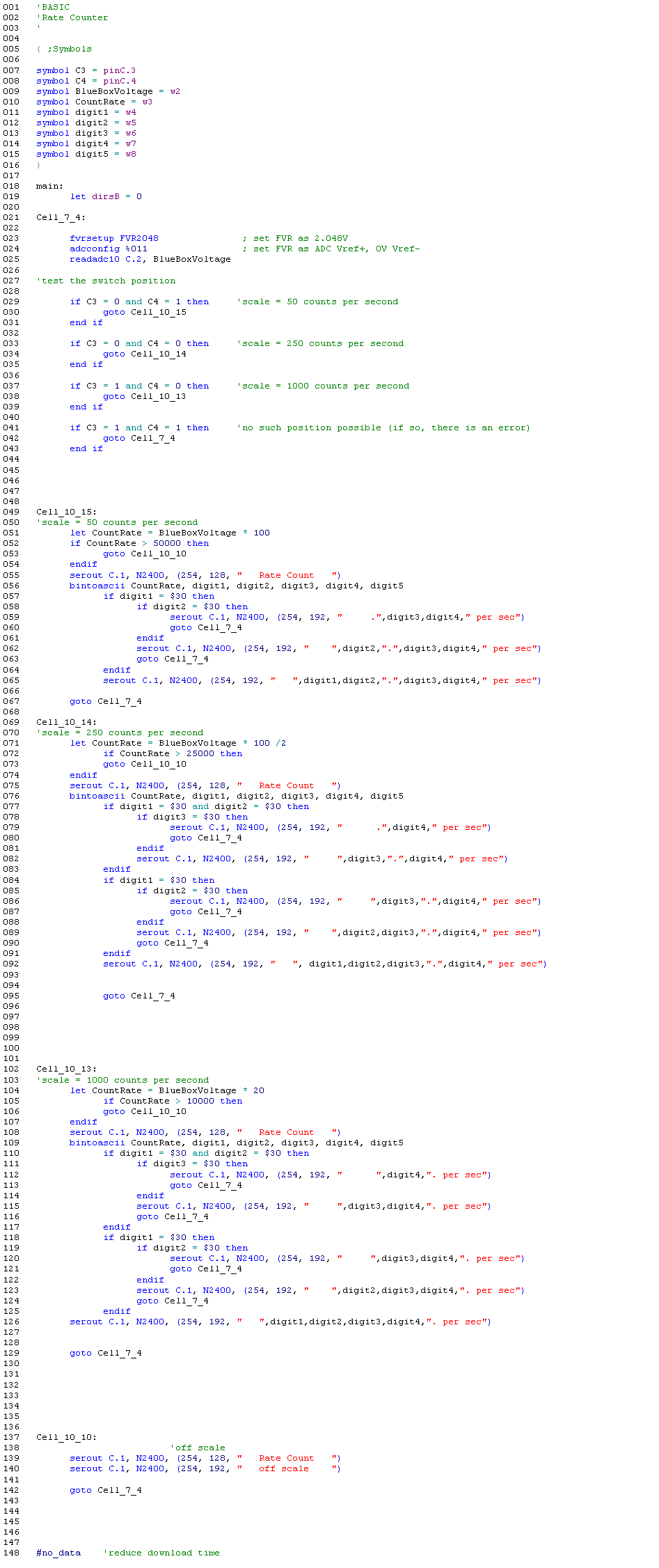
Solution |

|
Note on count rate The unit of radioactive decay in the System International Units (commonly known as the MKS system) is becquerel, which is one decay per second. This refers to the disintegration of a sample of radioactive material at the source. Another common unit of decay rate is the curie, which is 3.7 x 10^10 becquerel.
However, the count rate as determined with a Geiger-Müller tube is not quite the same as the decay rate. The G-M tube only detects that fraction of the decay products which are incident on the tube. Since the products of the decay may be emitted in all directions the Geiger-Müller tube count rate is not an accurate measure of the decay rate. Furthermore, the G-M tube may not detect all by-products of radioactive disintegration; for example, some G-M tubes may detect beta and gamma radiation, but not alpha radiation.
A Geiger-Müller tube connected to a rate counter is known as a Geiger counter. The rate sensor measures in units of counts per second (1/s). |
|
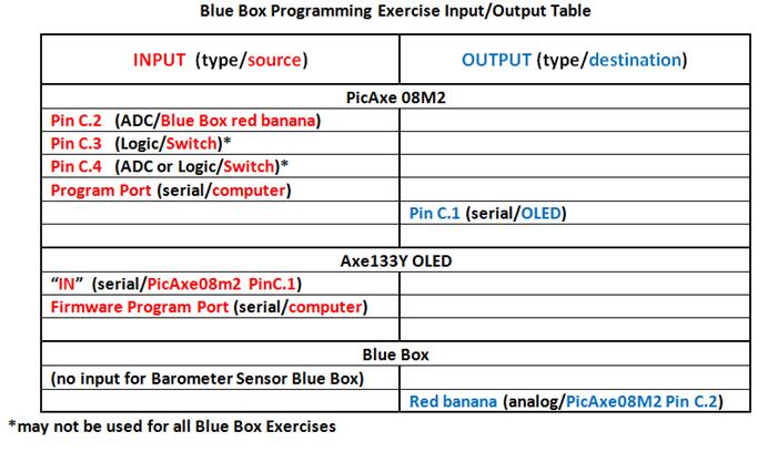
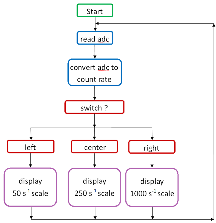
The Assignment The task here is to write a PicAxe program to read the analog input C.2, convert that to count rate, continuously update and display the result on the OLED. The OLED display must include the term “Count Rate” centered on the first line. The second line must display – centered – “Rate = “, followed by the current rate with its proper unit, 1/s. |
|
Preliminary Tasks The logic of the toggle switch must be determined. NOTE: The Blue Box is separate and independent of the PicAxe microprocessor; thus the switch selection on the Blue Box is not automatically reflected in the microprocessor. The purpose of the toggle switch in front of the OLED is to correlate the scale within the microprocessor program to the Blue Box scale. To display the count rate properly on the OLED the toggle switch position must be programmed into the PicAxe and the switch position must match the switch on the Blue Box.
The Solution The simplest solution is to write a Flowchart in Logicator first, then convert the Flowchart into Basic language. Inevitably, the Flowchart will not be complete so a modification of the program will be necessary. Use Programming Editor 6 to complete the program. The Flowchart might look something like this: |
|
Some PicAcxe Basic Commands First, define some variables such as these: symbol variablename = pinC.2 ‘for example symbol Counts = w0 ‘w0 and w1 are word variables, i.e., 16 bit symbol Rate = w1 symbol ToggleInput3 = pinC.3 ‘defines both variable name and which pin it represents symbol ToggleInput4 = pinC.4 ‘no space between the “n” and the “C” in the command
Commands related to reading the analog or digital logic input: fvrsetup FVR2048 adcconfig %011 readadc10 C.2 if variablename = 1 then (etc.) ‘this statement reads the input to check the “if” logic; ‘variablename must be defined with “symbol” statement; ‘”if” query is true when pin is high Commands related to displaying the output: bintoascii serout C.1, N2400_4,(254, 128,” “) serout C.1, N2400_4,(254, 192, “ “,b9,b10,b11,” “) Note that whatever is within the parenthesis is displayed on the OLED. Make sure that there are exactly 16 characters and/or spaces within the parenthesis. 128 is the leftmost position on line 1 of the OLED 192 is the leftmost position of line 2 of the OLED bintoascii converts a bit number to a display character. Commands related to logic and math: if variablename = 0 then endif goto (line name) Two logical conditions are necessary in order to determine the switch position. if pinC.3 = ? (high or low) and if pinC.4 = ? (high or low) then . . . . endif |
|
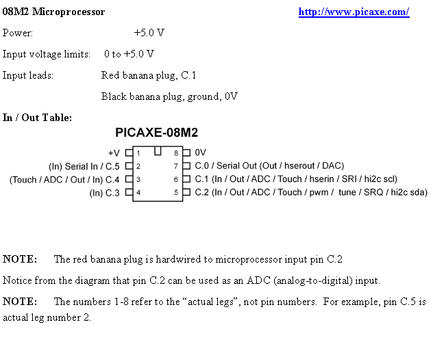
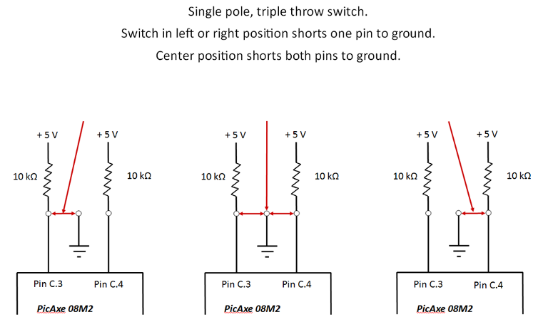
Toggle Switch (in front of the OLED) Three position toggle switch – single pole, triple throw. Switch is hardwired to – and switch logic is read at – Picaxe microprocessor pins C.3 and C.4 Black lead connected to ground, 0V / Orange lead hardwired to PicAxe microprocessor pin C.3 and blue lead hardwired to PicAxe microprocessor pin C.4 To find the logic of the switch, use a voltmeter on the microprocessor actual leg of pins C.3 and C.4 (check the PicAxe pin-out diagram, and be careful not to short other actual legs). Zero volts means logic state “low”, or 0; +5.0 V means logic state “high”, or 1. Use two logical conditions to determine the position of the switch. |
|
Switch circuit diagram: |
|
Switch circuit analysis: If the switch is in the position as shown in the left diagram, pin C.3 is shorted to ground and is thus low. Pin C.4 is connected to the +5.0 V power supply (no current through the 10KΩ resistor) and is thus high. In the right diagram, the conditions are reversed: pin C.3 is high and pin C.4 is low. In the center diagram, both pins are low. (no debounce protection) |
|
Philip Harris Rate Sensor Blue Box Use only the red and black banana jack connectors on the Blue Box. Never use the blue banana jack.
Power requirements: +6.0 V; separate external battery pack Battery pack red lead positive/Black lead ground, 0V Output (red/black banana jacks): Output ranges from 0 Volts to +1 Volt, and is linear in count rate. Red jack, voltage out; Black jack, ground, 0V. Switch in “BATT” position: The Blue Box output will be +1.0 V if the battery voltage is +6.0 V. Replace batteries if this output is below +0.75 V (corresponding to a battery voltage of +4.5 V). Three scales, switch selected, correspond to a count rate of 50 1/s, 250 1/s and 1000 1/s.
NOTE: The Blue Box scale switch selection must match the toggle switch selection for the output to display the count rate correctly on the OLED. NOTE: Do not use blue banana jack – negative voltage on the PicaAxe input may damage the microprocessor. |
|
|


|
|
Switch Left |
Switch Center |
Switch Right |
|
Logic state of pin C.3 (high or low) |
|
|
|
|
Logic state of pin C.4 (high or low) |
|
|
|