
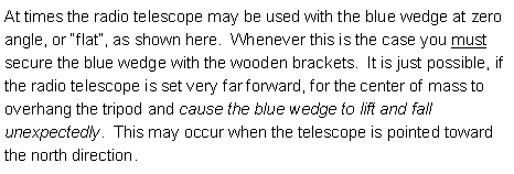
|
EOS |
|
Instruments |

|
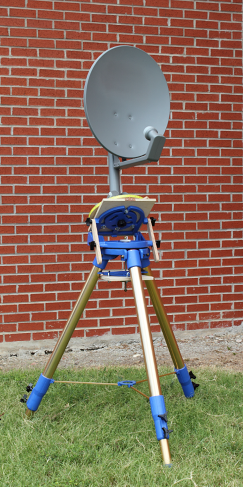
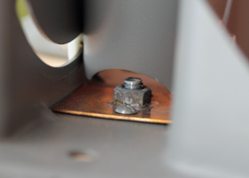
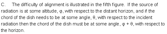
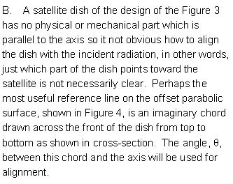
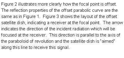
Part A.
How to Set Up the de l’Est Observatoire Solaire Radio Telescope |
|
Radio Telescope |
|
Radio Telescope |
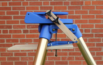
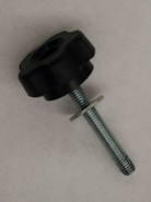
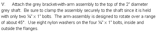
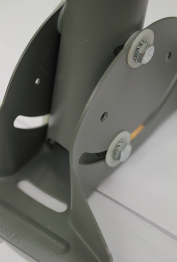
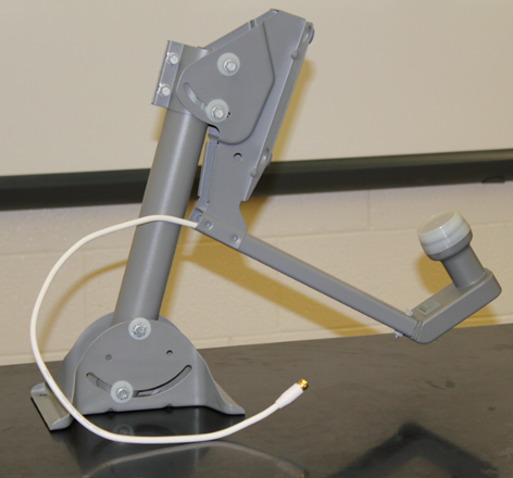
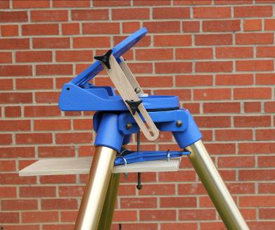
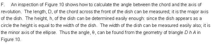
![Text Box: II. Attach the Lazy Susan base to the blue wedge. Use four 5/16” x 1” bolts. Before tightening, insert the 5/16” x 2 ¼” clamping bolt (with the 5-star knob) from the underneath side of the blue wedge just to make sure it aligns smoothly with the center hole of the Lazy Susan. [The blue wedge won’t lie in the flat position with this clamping bolt inserted.]
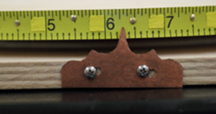
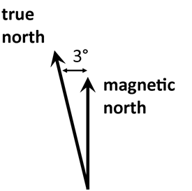
Also, use a compass to make sure that the center line of the Lazy Susan base is aligned along the north-south direction. True north is 3° west of magnetic north in Oklahoma.](RadioTelescope_files/image322.png)
|
Tools useful in the assembly of this radio telescope: 7/16” open end wrench 1/2” open end wrench 7/16” socket and ratchet Compass Small screwdrivers |


![Text Box: How to Import the US Naval Observatory Table into a Spreadsheet
How to turn a table from the US Naval Observatory website into usable data for LoggerPro or Graph
////////////////////////////////////////////////////////////////////////////////////////////////////////////
From this webpage: http://aa.usno.navy.mil/data/docs/Dur_OneYear.php#notes
How to Import the Table into a Spreadsheet
Open your favorite text editor, then copy the numerical part of the table (i.e., do not copy the table headings) from your browser and paste it into the text editor. Save the data as a text file.
In Excel 2003, click Data on the menu bar, then Import External Data, then Import Data. Select your saved text file. Choose fixed width in the dialog box. [In Excel 2004 for Mac, the commands are Data -> Get External Data -> Import Text File]
In Excel 2007, click Data on the menu bar, then From Text. Select your saved text file. Choose fixed width in the dialog box.
/////////////////////////////////////////////////////////////////////////////////////////////////////////////
Notes:
Favorite text editor = Notepad
Which can be found here:
Start>>All Programs>>Accessories>>NotePad
Save these as text files here:
Documents>>Astronomy>>RadioTelescope
Then open Excel and follow instructions to import the text file as data. Just keep clicking Next and it should work.
Then open LoggerPro, copy the altitude and/or azimuth columns from Excel and paste it/them into a data column. For the x-axis in LoggerPro, open Data>>New Manual Column, then click the Generate Values box; use increment either 1 or 10 minutes as necessary.](RadioTelescope_files/image414.png)

|
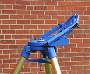
North Tripod mount for use with radio telescope. |
|
USNO Sun’s Altitude/Azimuth calculation page: |
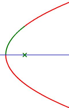
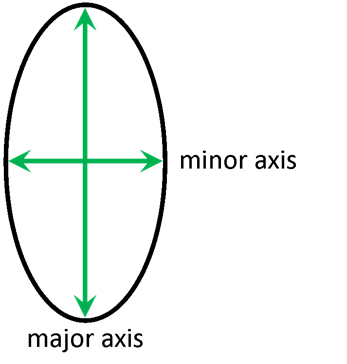
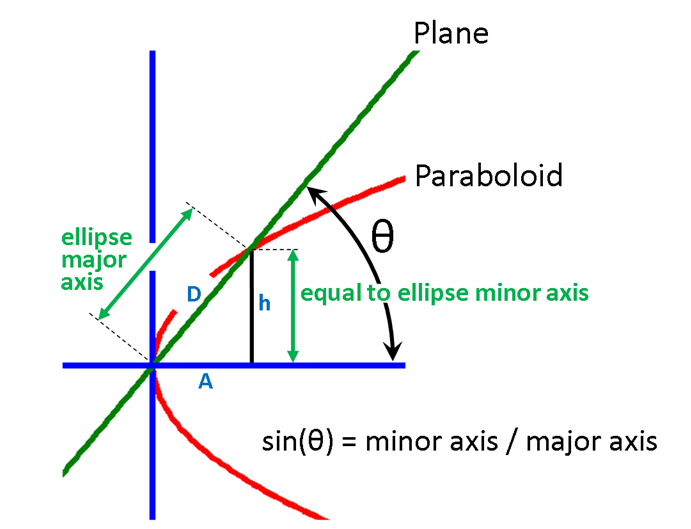
![Text Box: D. Paraboloid property #1 (or, rather, unproved assertion #1). Consider the intersection between a plane, blue in Figure 6, and a paraboloid of revolution. If the axis of revolution is perpendicular to the plane then the intersection will be a circle. If the axis of revolution is in the plane then the intersection will be a parabola (as shown in cross-section in Figure 1. However, if the plane is obtuse to the axis of revolution, as in Figure 6, then the intersection is an ellipse [property #1]. Thus, the outline of the offset satellite dish is an ellipse. The long way across an ellipse is called the major axis and the short way across is the minor axis as shown in Figure 7. The red chord in Figure 4 is the major axis of the elliptical rim of the satellite dish.](RadioTelescope_files/image352.png)
|
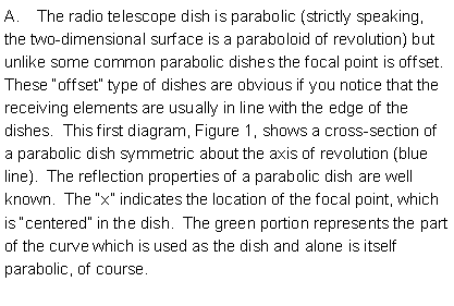
Part B.
How to Aim the de l’Est Observatoire Solaire Radio Telescope |
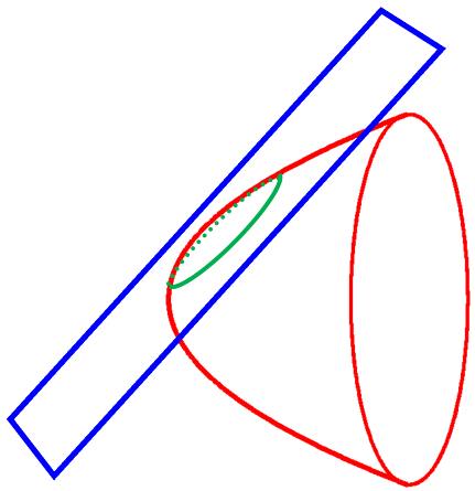
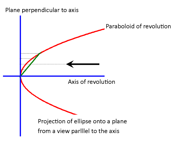
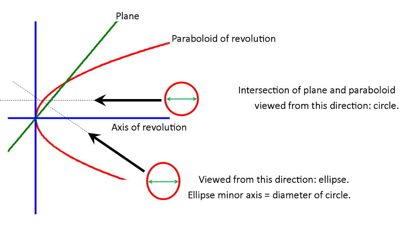
![Text Box: E. Paraboloid property #2 (unproved assertion #2). Everyone knows that a circle viewed from an obtuse angle may appear as an ellipse. Perspective drawing on a two-dimensional canvas relies on this illusion. It is also true that an ellipse, looked at from a certain angle, appears as a circle. If Figure 7 is printed onto a piece of paper, then it will appear as a circle if the direction of view is a very low angle just above the paper (look along the direction of either axis). This illusion occurs because the outline appears as though it were projected onto a plane perpendicular to the line of sight. If the elliptical outline of the intersection between an obtuse plane and a paraboloid of revolution is projected onto a plane perpendicular to the axis of rotation, the result is a circle [property #2]. This is illustrated in Figure 8. Figure 9 shows two views of the dish. In one view the dish appears as a circle. The other view is from the direction perpendicular to the chord.](RadioTelescope_files/image402.png)
![Text Box: Part II Application
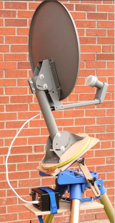
To track the sun with the radio telescope (no motor; track by hand):
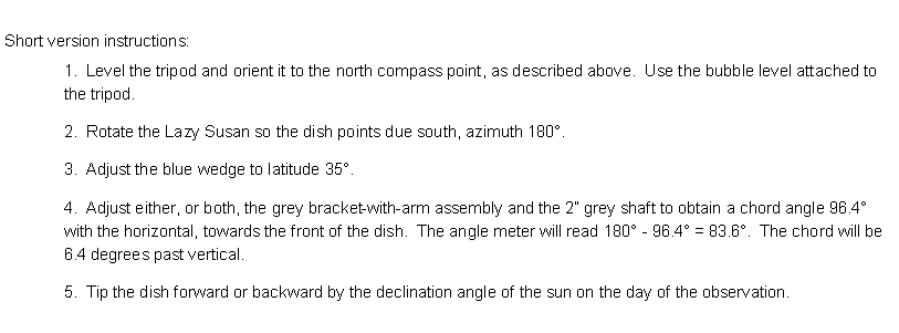
1. Level the tripod and orient it to the north compass point, as described above. Use the bubble level attached to the tripod.
2. Rotate the Lazy Susan so the dish points due south, azimuth 180°.
3. Remove the lower bolt of the grey bracket-with-arm assembly (at the top of the 2” grey shaft). Adjust the angle so that the 45 degree mark aligns with the center of the nut.
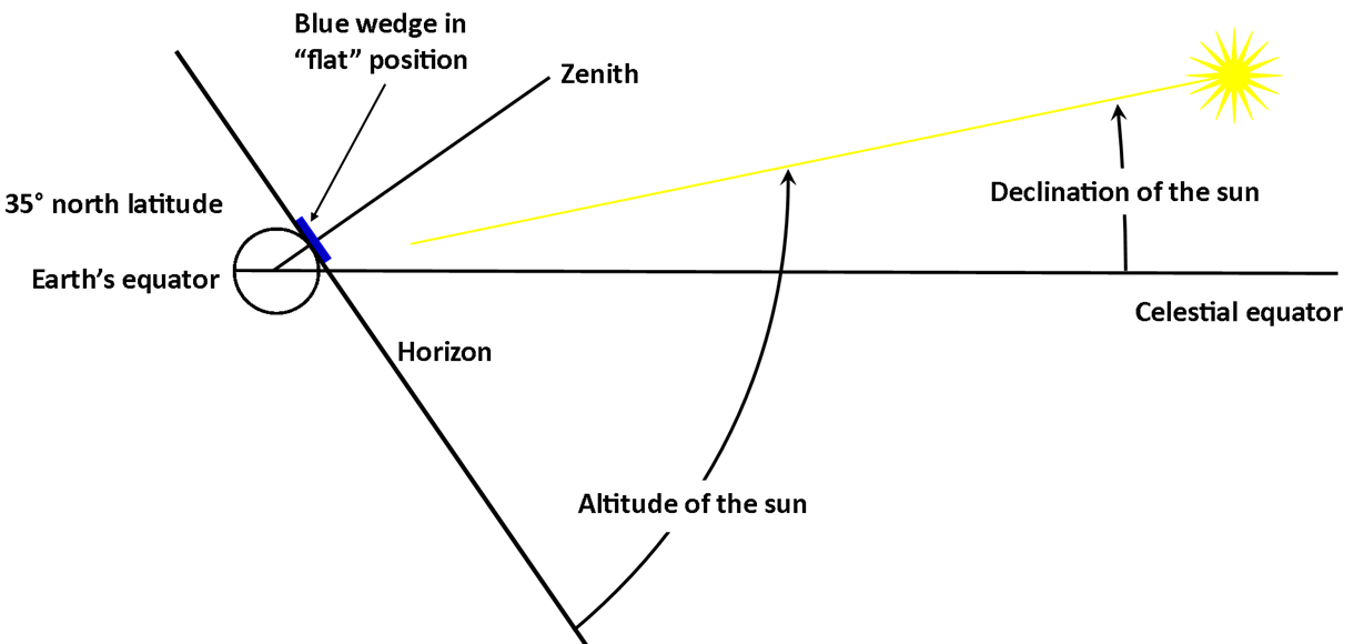
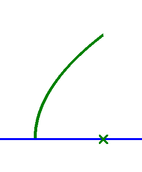
4. Use the grey square-steel tube as a cord across the front of the dish from top to bottom as shown in figure 4. Place the digital angle meter on the grey square-steel tube and tip the 2” grey shaft so the chord is at an angle of 61.4° with the horizontal (towards the front of the dish). The angle meter will read 180° - 61.4° = 118.6. The dish is now pointed at the horizon. See figure below.
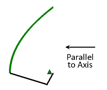
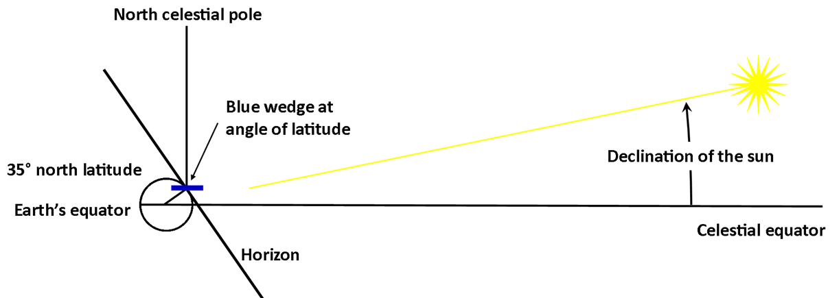
5. Place the angle meter along the center line of the Lazy Susan and tip the blue wedge to an angle equal to the latitude. At EOS, that angle is 34.9°. Secure the wedge with the wood brackets. This adjustment makes the tripod a German equatorial mount. See figure.
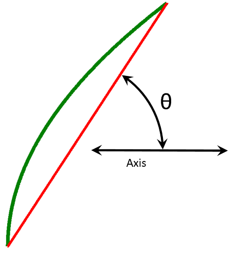
6. Now the dish is pointed at the celestial equator. The chord across the front of the dish will be at an angle of 61.4° + 34.9° = 96.3° with respect to the horizontal (towards the front of the dish), although the angle meter will read 180° - 96.4° = 83.6°. The chord will be 6.4 degrees past vertical.
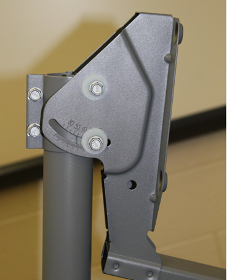
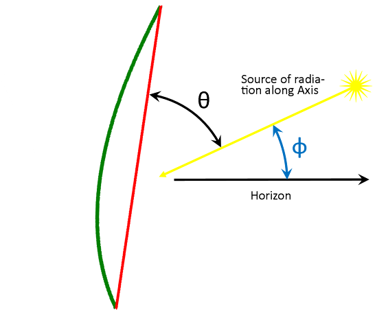
7. In order to aim the radio telescope at the sun, now rotate the grey bracket-with-arm assembly (either up or down) to an angle equal to the sun’s declination on the day of the observation. The range of declination values over the course of one year is ± 23.44° . The dish may now track the sun if the Lazy Susan is rotated. To keep the dish from turning inadvertently, use the five-star knob, and/or place the rubber and cork wedges under the Lazy Susan.
Find the declination.
The declination of the sun may be found in a number of ways.
A. Use the calculator found at the NOAA website.
http://www.esrl.noaa.gov/gmd/grad/solcalc/
Or try this old version. To use this version the latutide and longitude of the dish location are required.
http://www.esrl.noaa.gov/gmd/grad/solcalc/azel.html
B. Use a good planetarium program such as Starry Night. To use that particular program, first make sure that the time is set to the correct day.
1. Place the cursor on the sun. If the cursor is properly on the sun, information about the sun will appear in the upper left corner of the screen. Now, right-click on the sun, then left-click on “Select Sun”.
2. Now left-click on the “Info” tab along the left side of the screen; a box will open. The top line of the box should read “Name: Sun”. Scroll down to the box “Position in the Sky” and read the entry:
Dec (JNow)
C. Calculate the declination using an approximate equaton, such as this one:
δ ≈ -arcsin[0.39779*cos(0.98565*{N+10}+1.914*sin(0.98565*{N-2}))]
where N is the number of days from midnight UTC, January 1, to the day of the observation. Integer days should be accurate to within the ability to adjust the dish angle; however, fractional days will give greater accuracy in the declination. Be sure your calculator or math software is working in degrees, not radians.](RadioTelescope_files/image409.png)
|
Step 3. Remove the lower bolt. Adjust the angle so that the 45° mark aligns with the center of the nut. |
|
N = day of the year = cumulative days + day of the month
January N = day of the month February N = 31 + day of the month March N = 59 + day of the month (for non-leap year) April N = 90 + day of the month May N = 120 + day of the month June N = 151 + day of the month July N = 181 + day of the month August N = 212 + day of the month September N = 243 + day of the month October N = 273 + day of the month November N = 304 + day of the month December N = 334 + day of the month
For leap years, 2016, etc., add one to the cumulative days for March or later months) |
|
Fig. 1 |
|
Fig. 2 |
|
Fig. 3 |
|
Fig. 4 |
|
Fig. 5 |
|
Fig. 7 |
|
Fig. 6 |
|
Fig. 8 |
|
Fig. 9 |
|
Fig. 10 |
|
sin (θ) = h/D, or, θ = arcsin(h/D) = arcsin(minor axis/major axis). |
|
Step 4. Blue wedge in flat position and dish is aimed at the horizon. |
|
Step 5. Blue wedge adjusted to an angle equal to the latitude. Dish is now aimed at the celestial equator.
The next step, 7: To aim the dish at the sun, tip the dish an angle equal to the sun’s declination. |
|
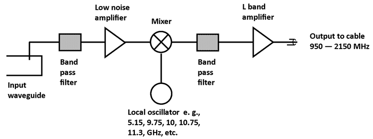
Input frequency band from satellite waveguide |
Input band GHz |
Local Oscillator (LO) frequency GHz |
Output L band into cable MHz |
Comments |
|
C band |
3.4-4.2 |
5.15 |
950-1750 |
inverted output spectrum |
|
|
3.625-4.2 |
5.15 |
950-1525 |
" |
|
|
4.5-4.8 |
5.75 |
950-1250 |
" |
|
|
4.5-4.8 |
5.95 |
1150-1450 |
" |
|
|
|
|
|
|
|
Ku band |
10.7-11.7 |
9.75 |
950-1950 |
|
|
|
10.95-11.7 |
10 |
950-1700 |
|
|
|
10.95 - 12.15 |
10 |
950-2150 |
Invacom SPV-50SM |
|
|
11.45-11.95 |
10.5 |
950-1450 |
|
|
|
11.2-11.7 |
10.25 |
950-1450 |
|
|
|
11.7-12.75 |
10.75 |
950-2000 |
Invacom SPV-60SM |
|
* |
12.25-12.75 |
11.3 |
950-1450 |
Invacom SPV-70SM |
|
|
11.7-12.75 |
10.6 |
1100-2150 |
|
|
|
|
|
|
|
|
Ka band |
19.2-19.7 |
18.25 |
950-1450 |
|
|
|
19.7-20.2 |
18.75 |
950-1450 |
|
|
|
20.2-20.7 |
19.25 |
950-1450 |
|
|
|
20.7-21.2 |
19.75 |
950-1450 |
|
|
|
19.7-20.2 |
21.2 |
1000-1500 |
Inverted |
|
|
18.2-19.2 |
17.25 |
950-1950 |
Norsat 9000 |
|
|
19.2-20.2 |
18.28 |
950-1950 |
Norsat 9000 |
|
|
20.2-21.2 |
19.25 |
950-1950 |
Norsat 9000 |
|
nominal 18” grey DishTV brand satellite dish |
||
|
Minor axis = 18.0” = 457.2 mm |
Major axis = 20.5” = 520.7 mm |
θ = 61.4° |