
|
EOS |
|
Instruments |

|
Light Sensor |
|
Programming Exercise in PicAxe |
|
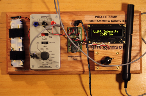
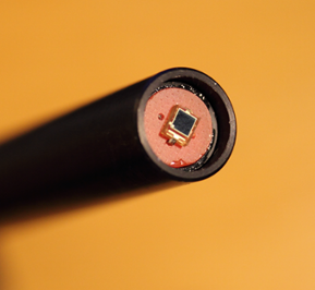
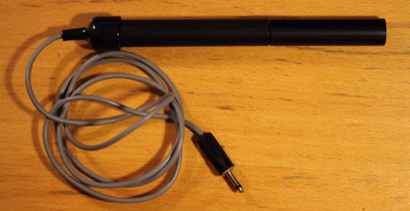
The output of the Philip Harris Linear Light Sensor is directly proportional to the intensity of the light per unit area at the probe. The sensor element, area about 4 square millimeters, is at the end of the probe. The element can be shielded somewhat from ambient light with the probe’s extendable tube. Light intensity in lux is measured on eleven linear scales and one log scale covering the overall range. For each of these twelve scales the Blue Box output voltage range is 0 to +1V. For the eleven linear scales the slide switch must be in either the FAST or SLOW position; this is a Blue Box internal circuit selection and no control external to the Blue Box is necessary. To use the Blue Box on the log scale the slide switch must be in the LOG position, as well as the rotary switch. |
|
See one of the other Blue Box Sensor pages for information about or examples of: Some PicAcxe Basic Commands useful for the solution Axe 133Y Serial OLED |

|
Note on units of light intensity The System-International (SI, commonly known as the MKS system) unit of luminous flux, the light given off by a source in a particular direction, is the candela (cd). The candela is a measure of emitted power per unit solid angle (steradian) with units watt/steradian. (Keep in mind that steradian is an angle measurement without unit.) Although the candela is precisely defined, of course, it is roughly equivalent to the amount of light power emitted by a single candle over a given solid angle. A lumen, on the other hand, is the power of the light emitted; that is, the luminous flux (in candela) times the solid angle over which the light is emitted: candela*steradians. The unit candela*steradian is equivalent to watt. The luminosity of an object (such as a star or lightbulb) is taken as the total power emitted. In that case the solid angle would be 4π steradians. Lux is a unit of light intensity which measures the amount of light power that illuminates a surface. That is, lux is the number of lumens per unit area, with unit watt/m^2. Lux is a commonly used unit in light meters. A unit similar to lux in the Imperial System is the footcandle; 1 ft candle being 10.764 lux. |
|
The logic of the rotary switch must be determined for either assignment.
NOTE: The Blue Box is separate and independent of the PicAxe microprocessor; thus the switch selection on the Blue Box is not automatically reflected in the microprocessor. The purpose of the rotary switch in front of the OLED is to correlate the scale within the microprocessor program to the Blue Box scale. To display the light intensity properly on the OLED the rotary switch position must be programmed into the PicAxe and the switch position must match the switch on the Blue Box. |
|
The Solution The simplest solution is to write a Flowchart in Logicator first then convert the Flowchart into Basic language. Inevitably, the Flowchart will not be complete so a modification of the program will be necessary. Use Programming Editor 6 to complete the program. Use “if” commands to detect all twelve of the rotary switch positions for the Light Sensor, Linear program, but only the rotary switch position LOG need be detected for the Light Sensor, Log program (all of the other switch positions can be lumped together as one). A. Light Sensor, Linear Program the eleven linear scales to display the light intensity, but skip over the log scale by displaying a simple message – something like “log scale”. The Flowchart for Light Sensor, Linear might look like this: |
|
The Assignment
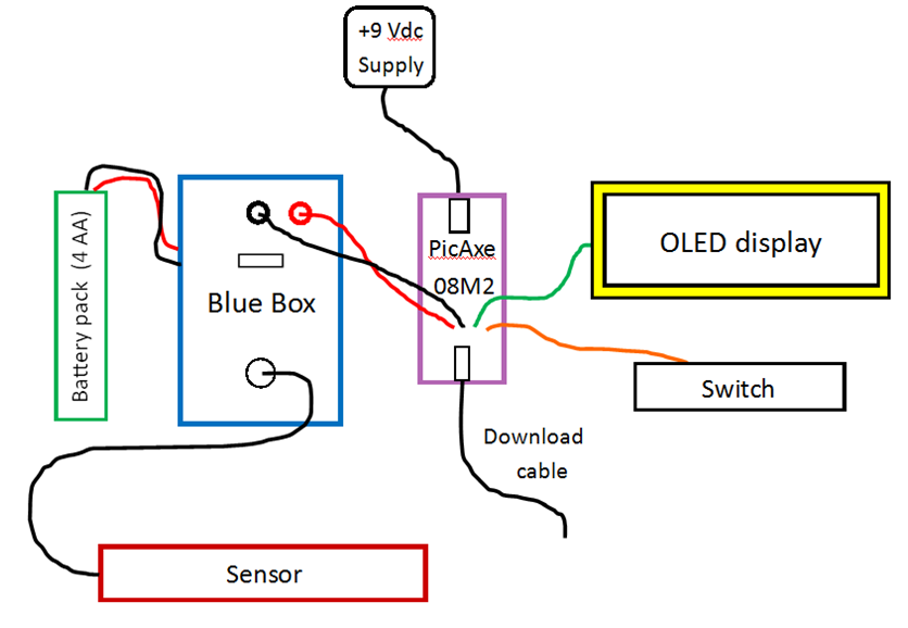
The task here is to write a PicAxe program to read the analog input C.2 with an analog-to-digital converter pin of the 08M2, convert that reading to light intensity in lux and continuously update and display the result on the OLED. The OLED display must include the term “Light Intensity” on the first line. The second line must display the current value followed by the proper unit (lux or kilolux).
The PicAxe 08M2 is a small microprocessor and consequently has a limited program memory. This restricts the number of lines of programming that can be downloaded to the chip. Because there are so many scales, the assignment tests this programming limit. Efficient programming techniques may be necessary to complete the assignment. To restrict the amount of programming for this exercise the task is divided into two individual assignments.
Light Sensor, Linear Use only the eleven linear scales, from 1 lux to 100 kilolux.
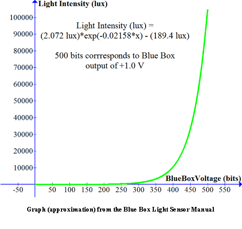
Light Sensor, Log Use only the log scale. On this scale the slide switch “LOG:FAST:SLOW” must be in the LOG position. Both the rotary switch on the Blue Box and the rotary switch in front of the OLED display must be in their respective LOG positions. The Blue Box output, maximum value +1.0V, covers the entire range which the eleven linear scales cover. Divide this range of light output into ten regions and use a linear approximation over each of the regions. See graphs below. |
|
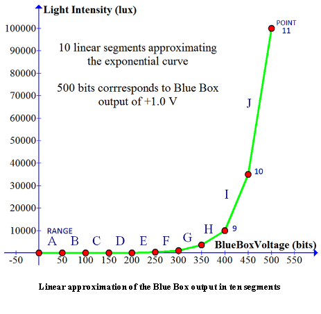
B. Light Sensor, Log Program only the LOG scale to display the light intensity. The actual log scale can be found in the Blue Box Light Sensor Linear Manual. Given here is an approximation of that scale; the first is a plot of data points taken from the graph, along with an exponential fit to that data. Shown in the second plot is a ten-segment linear approximation of the curve. Program the microprocessor with “if” commands to distinguish the ten regions of the scale and display the output as a linear approximation over each range. Find the slope and y-intercepts of the ten line segments to make the conversion from ADC input in bits (500 bits corresponds to +1.0 V Blue Box Voltage output if programmed to the maximum sensitivity – see instructor for details) to light intensity in lux (or kilolux). Keep in mind that PicAxe mathematics is rather bizarre. The Flowchart for Light Sensor, Log might look something like this: |
|
point |
X (bits) |
Y (lux) |
|
1 |
0 |
1 |
|
2 |
50 |
3.5 |
|
3 |
100 |
10 |
|
4 |
150 |
35 |
|
5 |
200 |
100 |
|
6 |
250 |
350 |
|
7 |
300 |
1000 |
|
8 |
350 |
350 |
|
9 |
400 |
10,000 |
|
10 |
450 |
35,000 |
|
11 |
500 |
100,000 |

|
plot these points |
Range |
Slope |
y-intercept |
|
1, 2 |
0-49 A |
|
|
|
2, 3 |
50-99 B |
|
|
|
3, 4 |
100-149 C |
|
|
|
4, 5 |
150-199 D |
|
|
|
5, 6 |
200-249 E |
|
|
|
6, 7 |
250-299 F |
|
|
|
7, 8 |
300-349 G |
|
|
|
8, 9 |
350-399 H |
|
|
|
9, 10 |
400-449 I |
|
|
|
10, 11 |
450-500 J |
|
|

|
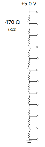
Rotary Switch (in front of the OLED) Twelve position rotary switch – single pole, 12 position. Switch circuit diagram (center connection not shown): |
|
Switch circuit analysis: The switch acts as a voltage divider. Eleven identical resistors in series divide the voltage evenly across each resistor. The output leg (not shown) of the switch is connected to the input pin C.4 of the microprocessor. The voltage input to the microprocessor varies from zero to +5.0 V as the switch is rotated. Each position of the switch represents a different scale. Use pin C.4 as an analog-to-digital input with the command readadc10. No debounce protection. |
|
Switch is hardwired to – and switch logic is read at – Picaxe microprocessor pin C.4 Black lead connected to ground, 0V / Red lead hardwired to +5.0 V White lead hardwired to PicAxe microprocessor pin C.4 To find the logic of the switch, use a voltmeter on the microprocessor actual leg of pin C.4 (check the PicAxe pin-out diagram, and be careful not to short other actual legs). Record the voltage at each switch position. |
|
Philip Harris Linear Light Sensor Blue Box Use only the red and black banana jack connectors on the Blue Box. Never use the blue banana jack. Power requirements: +6.0 V; separate external battery pack Battery pack red lead positive/Black lead ground, 0V Output (red/black banana jacks): Output ranges from 0 Volts to +1 Volt, and is linear in light intensity on eleven scales. The voltage output is proportional to the log (base 10) of the intensity on the scale labeled “log”. Red jack, voltage out; Black jack, ground, 0V. Switch in “BATT” position: The Blue Box output will be +1.0 V if the battery voltage is +6.0 V. Replace batteries if this output is below +0.75 V (corresponding to a battery voltage of +4.5 V). Twelve scales, switch selected. Eleven linear and one log. NOTE: The Blue Box scale switch selection must match the rotary switch selection for the output to display the field correctly on the OLED. NOTE: Do not use blue banana jack – negative voltage on the PicaAxe input may damage the microprocessor. |
|
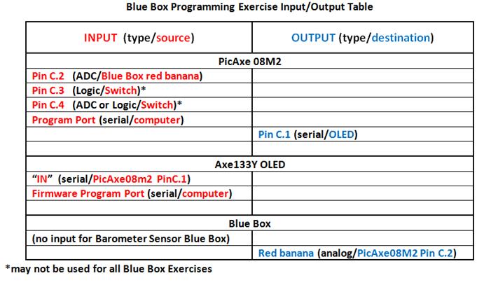
08M2 Microprocessor http://www.picaxe.com/ Power: +5.0 V Input voltage limits: 0 to +5.0 V Input leads: Red banana plug, C.2 Black banana plug, ground, 0V In / Out Table:
NOTE: The rotary switch selection must match the switch selection on the Blue Box for the output to display the light intensity correctly on the OLED. NOTE: The red banana plug is hardwired to microprocessor input pin C.2 Notice from the diagram that pin C.2 can be used as an ADC (analog-to-digital) input. Notice also that pin C.4 can be used as an ADC input. NOTE: The numbers 1-8 refer to the “actual legs”, not pin numbers. For example, pinC.5 is actual leg number 2. Details of the microprocessor and PicAxe Basic commands can be found at http://www.picaxe.com/docs/picaxe_manual2.pdf |
|
Switch (in front of OLED) Position |
Voltage at pin C.4 (Volts) |
|
Log |
|
|
100 k |
|
|
25k |
|
|
10k |
|
|
2500 |
|
|
1000 |
|
|
250 |
|
|
100 |
|
|
25 |
|
|
10 |
|
|
2.5 |
|
|
1 |
|