|
Geiger Counter |
|
Geiger Counter |

|
EOS |
|
Instruments |

|
Part A, Hardware. |
|
A PicAxe programming and hardware construction exercise.
The PicAxe 28X2 microprocessor drives an analog meter and an OLED in order to display the count rate of a Geiger tube. The scale is self-selecting within the program.
First the hardware is laid out, soldered together and assembled onto a breadboard. Then the program is written and downloaded onto the microprocessor. |
|
This project is based on the PicAxe 28X2 microprocessor and an obsolete SparkFun Geiger tube circuit. Using the PicAxe-28 Project Board is the simplest method to create a circuit for the counter.
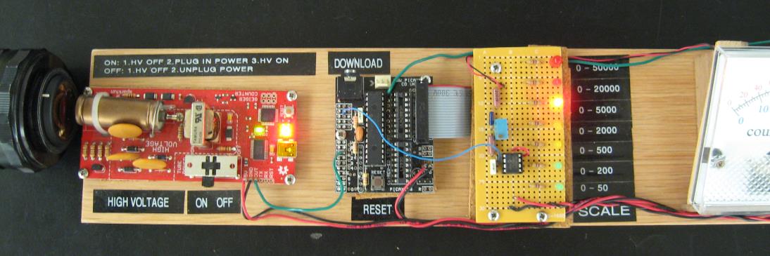
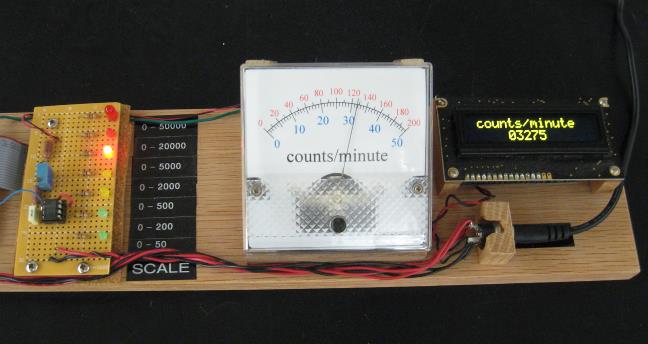
The Project Board and the Geiger tube circuit are mounted on a breadboard along with the OLED and the analog meter. A line of LEDs is used to indicate the analog meter scale.
|
|
Bill of Materials PicAxe 28X2 Project Board and 28X2 microprocessor SparkFun Geiger Counter SEN11345 (now obsolete)
Analog panel meter (50 μA max current) MPC6022 op amp 10 kΩ potentiometer 47k Ω resistor (2) 22kΩ resistors 100 nF capacitor 8-pin DIP socket
(6) 470 Ω resistors (6) LEDs
Wall power adapter, + 5 Vdc and matching panel mount jack. Breadboard, other mounting hardware and hook-up wire. |
|
Block Diagram of Geiger Counter
See the manufacturer’s datasheet for details regarding power connections for the 28X2.
http://www.picaxe.com/Hardware/Project-Boards/PICAXE-28-Project-Board/
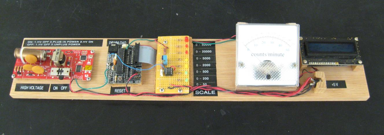
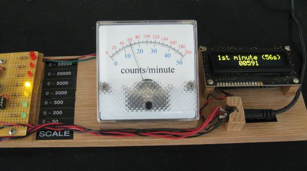
Below: least out-of-focus photograph extant of the completed breadboard. Note that this version has seven count-rate scales. |
|
PicAxe 28X2 |
|
SparkFun Geiger Counter circuit |
|
PicAxe 28 Project Board |
|
Op Amp driver for analog meter |
|
OLED |
|
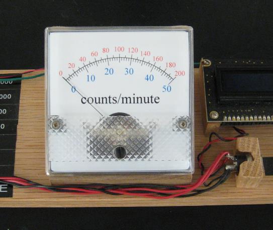
Analog meter |
|
Radioactive Tape Dispenser |

|
Radioactive Salt Substitute, KCl |
|
webpages and Eos image copyright 2018 M Nealon |
|
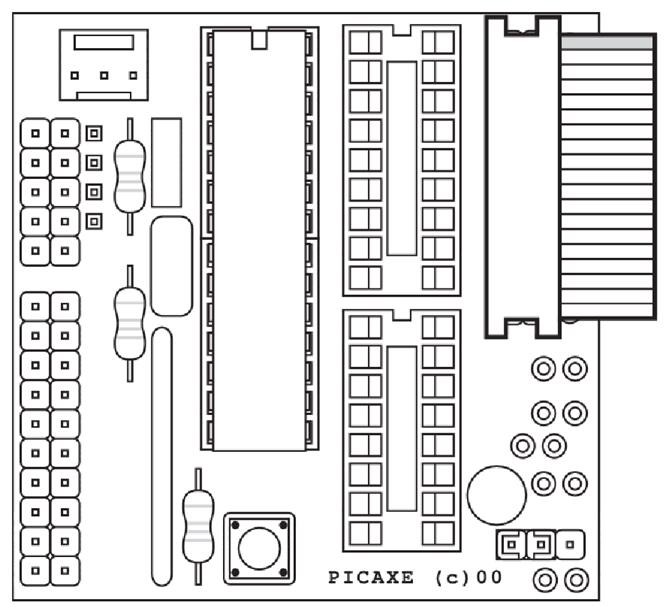
Connections to the Project Board
The output of the Geiger Couner circuit is connected to pin C.1 of the 28X2. The microprocessor output B.7 drives the OLED display, and Digital-to-Analog Converter (DAC) output A.2 connects to the operational amplifier which drives the analog meter.
Be sure to remove the Darlington driver chip, ULN2803A. Then, solder jumper wires from the microprocessor outputs B.0 through B.5 to the pins 11 through 16 on the socket as shown in the diagram above. These jumpers connect the microprocessor outputs directly to the ribbon cable connector. These jumpers may be soldered either on the top or the bottom of the Project Board. The ribbon cable connects the microprocessor outputs to a line of LEDs to indicate the analog meter scale. |
|
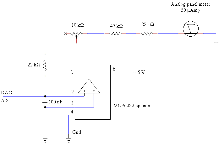
Schematic diagram of the analog meter driver.
The analog meter requires 50 microAmps to drive the pointer to its maximum position. Since the maximum output of the microprocessor is + 5 V, we may use Dr. Ohm’s law to calculate the resistance required to limit the current:
R = V/I = 5 (V) / 50 x 10-6 (A) = 100 kΩ.
In order that there be some leeway when calibrating the scale, we arrange for the total resistance be just over 100 kΩ. One kiloOhm should be enough leeway. Using resistors on hand, we have two 22 kΩ and one 47 kΩ resistors in series with a 10 kΩ potentiometer. The potentiometer is wired as a rheostat. Ten kiloOhms should be a wide enough range for adjustment.
To calibrate the meter:
First, with no voltage applied to the meter, the pointer is set to zero using the screw adjustment on the front panel of the meter. Next, a test program is written and downloaded so that the output A.2 is steady at its maximum value, nominally + 5 volts. The potentiometer is then adjusted so that the pointer is at maximum on the analog scale.
The maximum output of the DAC is not necessarily exactly equal to the power supply voltage. For details, see the Basic command in the PicAxe manual: DACsetup. http://www.picaxe.com/docs/picaxe_manual2.pdf
Note:
Both the SparkFun Geiger Counter circuit and the PicAxe Project Board will operate perfectly well with a battery pack of + 4.5 V. Whichever power supply voltage is used, however, the analog meter will require calibration at that voltage. |
|
Part B, Software. |
|
The scheme.
The overall plan of the program: count the events in the Geiger tube and display the counts-per-minute on both the OLED and the analog meter. Update the count every four seconds and auto-scale the displays.
The basic technique: count the events over a four second period and store the number in a wordvariable. Do this 15 times with 15 separate word variables. The sum of the 15 variables is the count per minute. |
|
The first minute.
The count per minute is not displayed during the first minute, but a cumulative count is displayed in four second increments until the one minute mark is reached.
Subsequent to the first minute.
The wordvariable containing the first of the four-second counts is refreshed with a new four-second count. This is added to the previous 14 four-second counts to give the counts per minute.
Each of the four-second counts is refreshed in turn in a continuous loop.
Pressing the reset button on the Project board will reset the program to begin a first minute count again. |
|
COUNT
Use the Basic command COUNT (see the PicAxe Manual).
This commands the microprocessor to count the pulses on the specified input pin during the specified time period and place the result in the specified worldvariable. Syntax: COUNT pin, period, worldvariable
Details of the COUNT command depend on the microprocessor clock speed.
Set the frequency of the microprocessor clock at 64MHz.
At this frequency, the pin is checked for a pulse every 2.5 μ seconds.
Also at this frequency the variable period must be written in multiples of 62.5 μ seconds. In order to make a four-second count, period = 64 000. (Again, see the Manual.)
count C.1,64000,w1
w1 is the name of the first of the 15 wordvariables used for the four-second counts.
The sum of the 15 wordvariables is the count rate.
Under no circumstances can the value of a wordvariable be greater than 65535. This means that, on average, each of the 15 wordvariables (with four second counts) may not have a value greater than 4369. This gives a maximum possible count rate of 1092 counts per second. If the count is that high, leave the building and call your indomitable instructor. |
|
download socket |
|
reset |


|
B.5 |
|
B.4 |
|
B.3 |
|
B.2 |
|
B.1 |
|
B.0 |
|
C.1 |
|
B.7 |
|
A.2 |
|
DAC to operational amplifier |

|
+ 5 V dc |
|
Gnd |
|
to OLED |
|
from Geiger tube circuit |
|
jumpers (x 6) |

|
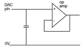
Analog output circuit; from the PicAxe manual.
The output A.2 is the Digital-to-Analog Converter output. The recommendation from the PicAxe manual is: op amp, MCP6022; capacitor, 100 nF. |
|
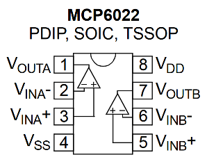
Op Amp pin output diagram; from the manufacture’s data sheet.
Pin 4, VSS, of the 8-Pin DIP is ground. Pin 8, V\DD, is the power supply; in this case, + 5 V dc. |
|
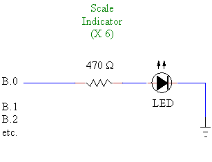
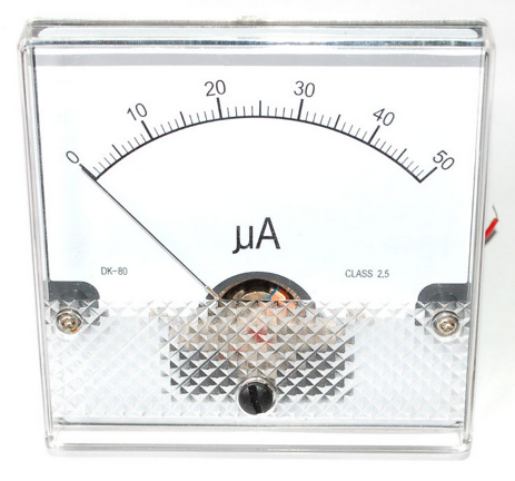
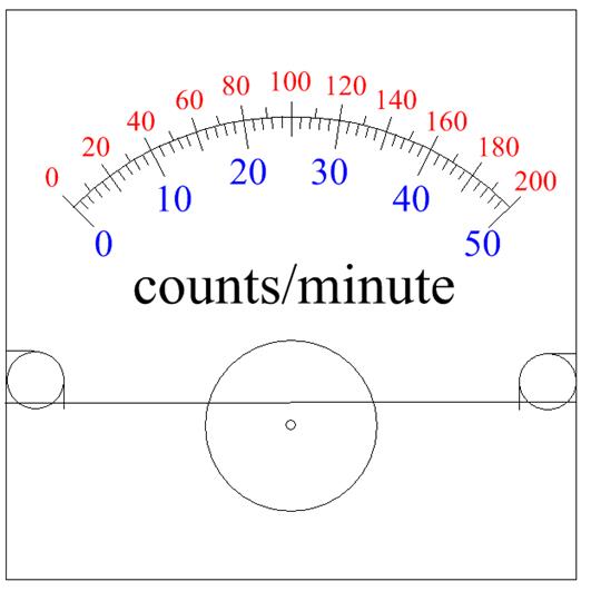
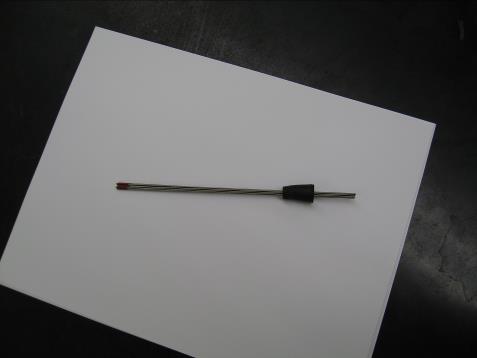
Scale Indicator Circuit for the Analog Meter.
To the right is shown the delicate analog d’Arsonval meter as received from the parts supplier. (Photo from AdaFruit.com) The meter housing is opened, the generic scale is removed and an appropriate printed scale is inserted in its place.
Below is shown the printed scale used in the finished Geiger Counter. This scale is created with drafting software and printed on photographic paper. Careful measurement of the meter’s original scale (along with trial and error) will assist in producing the correct size print.
The count rate scale is selected within the microprocessor program. However, we can think of the analog meter as simply registering a voltage from zero to + 5 volts regardless of the count rate scale. The scale to be read is indicated by one of the LEDs.
Scale Output LED (counts/minute)
0 — 50 counts/minute B.0 green 0 — 200 B.1 green 0 — 500 B.2 yellow 0 — 2 000 B.3 yellow 0 — 5 000 B.4 red 0 — 20 000 B.5 red |
|
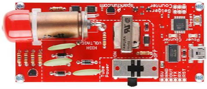
The SparkFun Geiger Circuit, model SEN-11345, now obsolete.
Make connections to the solder pads at the bottom of the red board labeled 5V, GND, and OUT.
The copper cylinder at the upper left of the board is the Gieger tube. The window is covered with a red plastic boot for protection during transit. This boot will block alpha particles, so the Geiger tube will detect alpha radiation only if the boot is off, but it will detect beta and gamma radiation whether the boot is on or off. (Photo from SparkFun.com)
The output is TTL active high whenever the Geiger tube detects an event. According to the old data sheet, the count per minute upper limit is as high as “100 Hz”. This corresponds to an upper limit of 6000 counts per minute. This means that the width of the output pulse is less than 167 μs. Probably much less.
https://www.sparkfun.com/products/retired/11345
Never touch the fragile end window of the Geiger Tube. Doing so will likely destroy the tube. |
|
'28X2 'rate counter, updates every four seconds 'microprocessor clock frequency 64 MHz; time interval for sampling 62.5 microsrconds; 64000 intervals for four seconds
pause 500 'wait for OLED to stabalize serout B.7,N2400,(254,1) 'clear display pause 30 serout B.7,N2400,(254,128," ") serout B.7,N2400,(254,192," ")
symbol activity = w0
symbol j=w16 symbol k=w17
'using w25, w26, w27 for bintoascii
symbol i=b44 'using w22, w23 for 8-bit variables symbol meterlevel=b45 'dac output level symbol varB=b46
init: low B.0 'LED indicators for analog scale low B.1 low B.2 low B.3 low B.4 low B.5 low B.6
activity = 0 'cumulative count variable i=0 'timestep index
dacsetup %10100000 'external DAC, pin A.2; supply voltage setfreq em64
'///////////////////////////////////////////////////////
main: gosub firstminutedisplay 'first thing to do is zero both meters gosub analogmeter
'first minute count accumulates in four second intervals; time is displayed count C.1,64000,w1
activity = w1 i=i+4 gosub firstminutedisplay gosub analogmeter
count C.1,64000,w2
activity = w1+w2 i=i+4 gosub firstminutedisplay gosub analogmeter
count C.1,64000,w3
activity = w1+w2+w3 i=i+4 gosub firstminutedisplay gosub analogmeter
count C.1,64000,w4
activity = w1+w2+w3+w4 i=i+4 gosub firstminutedisplay gosub analogmeter
count C.1,64000,w5
activity = w1+w2+w3+w4+w5 i=i+4 gosub firstminutedisplay gosub analogmeter
count C.1,64000,w6
activity = w1+w2+w3+w4+w5+w6 i=i+4 gosub firstminutedisplay gosub analogmeter
count C.1,64000,w7
activity = w1+w2+w3+w4+w5+w6+w7 i=i+4 gosub firstminutedisplay gosub analogmeter
count C.1,64000,w8
activity = w1+w2+w3+w4+w5+w6+w7+w8 i=i+4 gosub firstminutedisplay gosub analogmeter
count C.1,64000,w9
activity = w1+w2+w3+w4+w5+w6+w7+w8+w9 i=i+4 gosub firstminutedisplay gosub analogmeter
count C.1,64000,w10
activity = w1+w2+w3+w4+w5+w6+w7+w8+w9+w10 i=i+4 gosub firstminutedisplay gosub analogmeter
count C.1,64000,w11
activity = w1+w2+w3+w4+w5+w6+w7+w8+w9+w10+w11 i=i+4 gosub firstminutedisplay gosub analogmeter
count C.1,64000,w12
activity = w1+w2+w3+w4+w5+w6+w7+w8+w9+w10+w11+w12 i=i+4 gosub firstminutedisplay gosub analogmeter
count C.1,64000,w13
activity = w1+w2+w3+w4+w5+w6+w7+w8+w9+w10+w11+w12+w13 i=i+4 gosub firstminutedisplay gosub analogmeter
count C.1,64000,w14
activity = w1+w2+w3+w4+w5+w6+w7+w8+w9+w10+w11+w12+w13+w14 i=i+4 gosub firstminutedisplay gosub analogmeter
count C.1,64000,w15
activity = w1+w2+w3+w4+w5+w6+w7+w8+w9+w10+w11+w12+w13+w14+w15 i=i+4 gosub firstminutedisplay gosub analogmeter
'////////////////////////////////////////////////////////////////////////////////
begin:
'continous display in counts per minute after the first minute
count C.1,64000,w1
activity = w1+w2+w3+w4+w5+w6+w7+w8+w9+w10+w11+w12+w13+w14+w15 i=4 gosub analogmeter gosub display
count C.1,64000,w2
activity = w1+w2+w3+w4+w5+w6+w7+w8+w9+w10+w11+w12+w13+w14+w15 i=i+4 gosub analogmeter gosub display
count C.1,64000,w3
activity = w1+w2+w3+w4+w5+w6+w7+w8+w9+w10+w11+w12+w13+w14+w15 i=i+4 gosub analogmeter gosub display
count C.1,64000,w4
activity = w1+w2+w3+w4+w5+w6+w7+w8+w9+w10+w11+w12+w13+w14+w15 i=i+4 gosub analogmeter gosub display
count C.1,64000,w5
activity = w1+w2+w3+w4+w5+w6+w7+w8+w9+w10+w11+w12+w13+w14+w15 i=i+4 gosub analogmeter gosub display
count C.1,64000,w6
activity = w1+w2+w3+w4+w5+w6+w7+w8+w9+w10+w11+w12+w13+w14+w15 i=i+4 gosub analogmeter gosub display
count C.1,64000,w7
activity = w1+w2+w3+w4+w5+w6+w7+w8+w9+w10+w11+w12+w13+w14+w15 i=i+4 gosub analogmeter gosub display
count C.1,64000,w8
activity = w1+w2+w3+w4+w5+w6+w7+w8+w9+w10+w11+w12+w13+w14+w15 i=i+4 gosub analogmeter gosub display
count C.1,64000,w9
activity = w1+w2+w3+w4+w5+w6+w7+w8+w9+w10+w11+w12+w13+w14+w15 i=i+4 gosub analogmeter gosub display
count C.1,64000,w10
activity = w1+w2+w3+w4+w5+w6+w7+w8+w9+w10+w11+w12+w13+w14+w15 i=i+4 gosub analogmeter gosub display
count C.1,64000,w11
activity = w1+w2+w3+w4+w5+w6+w7+w8+w9+w10+w11+w12+w13+w14+w15 i=i+4 gosub analogmeter gosub display
count C.1,64000,w12
activity = w1+w2+w3+w4+w5+w6+w7+w8+w9+w10+w11+w12+w13+w14+w15 i=i+4 gosub analogmeter gosub display
count C.1,64000,w13
activity = w1+w2+w3+w4+w5+w6+w7+w8+w9+w10+w11+w12+w13+w14+w15 i=i+4 gosub analogmeter gosub display
count C.1,64000,w14
activity = w1+w2+w3+w4+w5+w6+w7+w8+w9+w10+w11+w12+w13+w14+w15 i=i+4 gosub analogmeter gosub display
count C.1,64000,w15
activity = w1+w2+w3+w4+w5+w6+w7+w8+w9+w10+w11+w12+w13+w14+w15 i=i+4 gosub analogmeter gosub display
goto begin:
'//////////////////////////////////////////////////////////////////
firstminutedisplay:
if activity > 50000 then goto line200 endif
setfreq m8 ‘OLED operates at 8MHz bintoascii i,b52,b53,b54 serout B.7,N2400,(254,128,"1st minute (",b53,b54,"s)") bintoascii activity,b50,b51,b52,b53,b54 serout B.7,N2400,(254,192," ",b50,b51,b52,b53,b54," ") setfreq em64 ‘return to 64MHz goto line300:
line200: setfreq m8 ‘OLED operates at 8MHz serout B.7,N2400,(254,128," danger ") serout B.7,N2400,(254,192," offscale ") setfreq em64 ‘return to 64MHz
line300: return
'//////////////////////////////////////////////////////////////////
display: if activity > 50000 then goto line400 endif
setfreq m8 bintoascii i,b52,b53,b54 serout B.7,N2400,(254,128," counts/minute ") bintoascii activity,b50,b51,b52,b53,b54 'using w25, w26, w27 serout B.7,N2400,(254,192," ",b50,b51,b52,b53,b54," ") setfreq em64 goto line500:
line400: setfreq m8 serout B.7,N2400,(254,128," danger ") serout B.7,N2400,(254,192," offscale ") setfreq em64
line500: return
'//////////////////////////////////////////////////////////////////
analogmeter:
'/////////////////////////////////////// scale 1; 0 - 50 counts/min
if activity <= 50 then high B.0 low B.1 low B.2 low B.3 low B.4 low B.5 low B.6
j = 0 k = 1 varB = 0
for meterlevel = 0 to 31
if j = 46 then 'k doesn't quite reach 50 without this k = 50 endif
if activity >= j and activity <= k then daclevel meterlevel exit endif
if varB = 0 then goto line600 endif j = j + 2 k = k + 1 varB = 0 goto line700
line600: j = j + 1 k = k + 2 varB = 1
line700: next meterlevel
endif
'/////////////////////////////////////// scale 2; 0 - 200 counts/min
if activity > 50 and activity <= 200 then low B.0 high B.1 low B.2 low B.3 low B.4 low B.5 low B.6
j = 0 k = 5 varB = 0
for meterlevel = 1 to 30
if activity >= j and activity <= k then
daclevel meterlevel exit endif
if varB = 0 then goto line610 endif j = j + 7 k = k + 6 varB = 0 goto line710
line610: j = j + 6 k = k + 7 varB = 1
line710: next meterlevel
endif
'/////////////////////////////////////// scale 3; 0 - 500 counts/min
if activity > 200 and activity <= 500 then low B.0 low B.1 high B.2 low B.3 low B.4 low B.5 low B.6
j = 0 k = 14 varB = 0
for meterlevel = 0 to 31
if k = 495 then 'k doesn't quite reach 500 without this k = 500 endif
if activity >= j and activity <= k then daclevel meterlevel exit endif
if varB = 0 then goto line620 endif j = j + 16 k = k + 15 varB = 0 goto line720
line620: j = j + 15 k = k + 16 varB = 1
line720: next meterlevel
endif
'/////////////////////////////////////// scale 4; 0 - 2000 counts/min
if activity > 500 and activity <= 2000 then low B.0 low B.1 low B.2 high B.3 low B.4 low B.5 low B.6
j = 0 k = 61 varB = 0
for meterlevel = 0 to 31
if k = 1999 then 'k doesn't quite reach 2000 without this k = 2000 endif
if activity >= j and activity <= k then daclevel meterlevel exit endif
if varB = 0 then goto line630 endif j = j + 63 k = k + 62 varB = 0 goto line730
line630: j = j + 62 k = k + 63 varB = 1
line730: next meterlevel
endif
'/////////////////////////////////////// scale 5; 0 - 5000 counts/min
if activity > 2000 and activity <= 5000 then low B.0 low B.1 low B.2 low B.3 high B.4 low B.5 low B.6
j = 0 k = 155 varB = 0
for meterlevel = 0 to 31
if activity >= j and activity <= k then daclevel meterlevel exit endif
if varB = 0 then goto line640 endif j = j + 157 k = k + 156 varB = 0 goto line740
line640: j = j + 156 k = k + 157 varB = 1
line740: next meterlevel
endif
'/////////////////////////////////////// scale 6; 0 - 20000 counts/min
if activity > 5000 and activity <= 20000 then low B.0 low B.1 low B.2 low B.3 low B.4 high B.5 low B.6
j = 0 k = 624 varB = 0
for meterlevel = 0 to 31
if activity >= j and activity <= k then daclevel meterlevel exit endif
if varB = 0 then goto line650 endif j = j + 626 k = k + 625 varB = 0 goto line750
line650: j = j + 625 k = k + 626 varB = 1
line750: next meterlevel
endif
'/////////////////////////////////////// scale 7; 0 - 50000 counts/min
if activity > 20000 and activity <= 50000 then low B.0 low B.1 low B.2 low B.3 low B.4 low B.5 high B.6
j = 0 k = 1561 varB = 0
for meterlevel = 0 to 31
if k = 49999 then 'k doesn't quite reach 50000 without this k = 50000 endif
if activity >= j and activity <= k then daclevel meterlevel exit endif
if varB = 0 then goto line660 endif j = j + 1563 k = k + 1562 varB = 0 goto line760
line660: j = j + 1562 k = k + 1563 varB = 1
line760: next meterlevel
endif
'/////////////////////////////////////// scale 8; over 50000 counts/min
if activity > 50000 then daclevel 0 low B.0 low B.1 low B.2 low B.3 low B.4 low B.5 low B.6
endif
'///////////////////////////////////////
return
#no_data #no_table |
|
to LEDs; indicating analog meter scale |
|
DAC
There is only one pin of the 28X2 on which the Digital-to-Analog Converter is available: A.2, which appears on actual leg 4 of the chip.
The Basic commands dacsetup and daclevel are required to use this feature (see the PicAxe Manual).
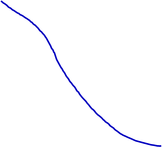
An analog voltage output is no so easy to produce in a microprocessor. Although the range may be set, typically the output voltage will range from zero to (nominally) the power supply voltage — in this case, + 5 volts.
The output resolution is not very high. In this PicAxe, the output voltage may be specified in 32 discrete steps (0 — 31); that is, for a + 5 V supply, each step is 0.156 volts. The maximum voltage output is 31/32 of the supply voltage.
Because the resolution is so low, changes in the output voltage look more like stair-steps than a smooth continuous function.
The purpose of the analog Operational Amplifier is to smooth out the DAC voltage output. Another purpose of the op amp is to provide enough current to drive the desired output device. The microprocessor DAC output cannot produce enough current for any practical purpose. (See dacsetup in the PicAxe Manual.)
The op amp is connected as a unity-gain follower. The 100nf capacitor acts as a filter to smooth the output voltage.
Commands
Syntax: dacsetup config
An example of DAC configuration: Let
config = %10100000
The % sign means that the microprocessor is to read the number which follows as an 8-bit binary number. The first 1 (bit 7, most significant bit) means that the DAC function is enabled. The second 1 (bit 5) means that the enabled DAC output overrides any input/output command to this pin. Bits 2 and 3 being zero mean that the upper limit of the output shall be the supply voltage. Bit 0 (least significant) means that the lower limit of the output shall be zero. Bits 1, 4 and 6 are unused and are thus ignored. This command is used once at the top of the program.
Syntax: daclevel level
where level is a number from 0 to 31.
For example, if level = 25, then the output voltage would be 25 x (5/32) = 3.906 volts. This command is used to set the DAC output voltage. |
|
DAC, part 2
“meterlevel” is the name of a variable that ranges from 0 to 31. This will become level in the daclevel command.
“activity” is the count rate.
The most convenient way to use the daclevel command is as follows:
The key is to convert the 32 DAC levels into counts-per- minute steps. As we then step through the DAC levels, we compare the counts-per-minute steps with “activity”.
To step through the DAC levels, use something like a “for/next” command:
for meterlevel = 0 to 31 . . . next meterlevel
We can test by “if” command whether “activity” is within a step of count rate values:
if activity >= j and activity <= k then . . . etc., where j and k define the boundaries of a DAC step in count rate units.
///////////////////////////////////\\\\\\\\\\\\\\\\\\\\\\\\\\\\\\\\\
First, however, we should determine which scale to use because the width of the step in counts-per-minute depends on the scale.
For example, if “activity” is, say, 4750 counts per minute, we want to display on Scale Five, zero-to-5000 counts per minute.
Use the “if” command to make the test. For example:
if activity > 2000 and activity <= 5000 then etc.
If this “if” is true, then light the LED on pin B.4 to indicate to an observer which scale to read.
\\\\\\\\\\\\\\\\\\\\\\\\\\\\\\\\\///////////////////////////////////
Once you know the scale, determine the DAC step in counts-per-minutes by dividing the maximum count rate by 32.
On the scale with a maximum activity of 5000 counts/min, we would have a step of 5000/32 = 156 counts/min.
The two indicies mentioned above, j and k, define the boundaries of this DAC step in count rate units. The range between j and k depends on which scale is in use.
In the example we are using, the interval between j and k is 156 counts/min. (This interval, or step width, may not be exactly uniform because we must fit 32 steps across the entire scale and we deal in integers only.)
If we let “meterlevel” = 0, the first DAC step, we would start with j = 0 and k = 155. The reason for this initial value of k will be obvious if a table of a few values of B, “meterlevel”, j, and k is constructed; see the table below. (B is merely an index: 0, or 1; see the program code.)
If “activity” falls between these values of j and k, then we define daclevel as “meterlevel”:
daclevel meterlevel
(= 0 in this case; therefore the output voltage = 0); that is: no deflection of the analog meter. There is no indication on the meter if the count rate is less than 155 counts/min on this zero-to-5000 scale. See what I mean about the low resolution in the DAC?
If “activity” is greater than 155 counts/min (but still within the zero-to-5000 scale), then the program increments “meterlevel” by 1, j by 156 and k by 157. At this point, j = 156 and k = 312. Now, “activity” is tested again to see whether it falls within this range.
If the count rate was not within that range, try the next “meterlevel”. This time, increment j by 157 and k by 156, and again test “activity”.
Step through “meterlevel” alternating the increments of j and k until “activity” is within the corresponding j to k range. |
|
“I have found you an argument, but I am not obliged to find you an understanding.”
Dr. Samuel Johnson |
|
The first minute |
|
Subsequent minutes |
|
Subroutine: analogmeter |
|
Subroutine: display |

|
The Program in Flow Chart Form |
|
Subroutine: firstminutedisplay |


|
START |
|
The Program (Instructor’s Solution)
In this instance, straightforwardness surpasses efficiency as a desirable characteristic. |
|
B |
meterlevel |
j |
k |
|
0 |
0 |
0 |
155 |
|
1 |
1 |
|
|
|
0 |
2 |
|
|
|
1 |
3 |
|
|
|
|
4 |
|
|
|
|
|
|
|
|
|
|
|
|

|
Existing OLED firmware requires a microprocessor clock speed of 8 MHz. The OLED firmware could be altered to allow the device to work at 64 MHz. This would obviate the need for the commands: setfreq m8 setfreq em64 before and after the serout commands. |
|
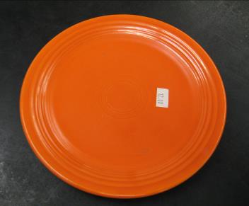
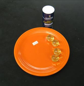
Radioactive Fiestaware. $12.00. Nice. |
|
Radioactive 2% Thoriated Tungsten welding electrodes. Bundle of ten mounted in a rubber stopper. |
|
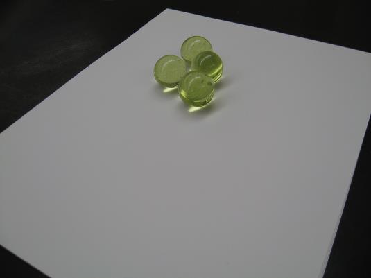
Radioactive Uranium glass marbles. |
|
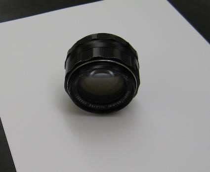
Radioactive Camera Lens. 1960’s. Japan. Probably thorium oxide mixed into the glass in order to control the index of refraction. |
|
Radioactive light supper. |

|
Instructions
To turn on the device: First, with no power, make sure the High Voltage switch on the red SparkFun Geiger Board is in the “OFF” position. Plug in the + 5 Volt power supply. Now turn on the HIGH VOLTAGE switch.
To turn off the device: First, turn off the HIGH VOLTAGE switch, then unplug the power. |
|
Radioactive Lens on the 0 - 5000 counts per minute scale. |
|
Radioactive Camera Lens. Count rate is shown on both the analog meter and the OLED. |
|
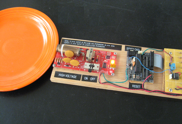
Above, Fiestaware under test.
Below, the Fiestaware count rate is shown after 56 seconds of the first minute. On the analog scale of 0 - 2000 counts per minute, the rate is shown to be just under 600 counts per, in this case, 56 seconds, matching closely the OLED reading. |