|
Measuring Inductance |


|
Measuring Inductance |

|
An inductor is just a coil of wire, usually copper. Winding a current carrying wire into a coil has the effect of impeding the flow of alternating current by inductive reactance. The copper wire itself has an ordinary dc resistance which cannot be separated from the coil’s reactance. They act together as impedance.
Inductors may be modeled by an equivalent circuit: an imaginary resistor in series with an ideal coil. Let the inductance of the coil be L, measured in Henrys, and the resistance of the coil be Rcoil. The impedance of the inductor, Zcoil, is its dc resistance in series with its inductive reactance, XL,
The inductive reactance depends on the frequency f, of the alternating current. Impedance, resistance, and reactance are measured in Ohms. |
|
Sometimes this dc resistance may be ignored – if it is small compared to other resistances in the circuit. If this is the case, the formula can be simplified by setting Rcoil equal to zero. |
|
Measuring Inductance
The simple method of determining the inductance of a coil is to put the coil in a series circuit with a known high precision resistor R, and drive the circuit with an ac source of known frequency. Then a measurement of the source voltage Vs, and the voltage across the coil Vcoil can be used to calculate the inductance. |
|
Derivation of the inductance formula
The resistor and coil in series have a total impedance of
These two passive elements, the inductor and resistor, act as a voltage divider with the total current in the circuit given by the source voltage divided by the total impedance.
But the current is also given by the voltage across the coil divided by its impedance.
Setting these two expressions equal, we have
|
|
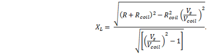
In order to remove j, find the magnitude of the impedance. To do this, square both sides and then take the square root. To square the imaginary number, multiply it by its complex conjugate
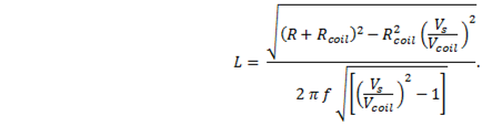
Now substitute the inductive reactance for the result
This is the formula for the general case. |
|
Simplify
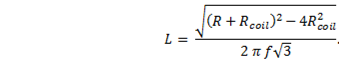
It is possible to simplify the measurement. With just the right combination of frequency and series resistance the voltage across the inductor Vcoil, may be found to be exactly one-half the source voltage Vs. If so, then Vs/Vcoil = 2, and the equation becomes
Now if the internal resistance of the coil can be neglected (still under the same condition Vcoil = ½ Vs) we have
|
|
If you use the same circuit but measure the voltage, VR, across the resistor, R, instead of the voltage across the coil, the condition VR = ½ Vs occurs at a different frequency. In this case, the formula is |