
|
EOS |
|
Instruments |

|
Magnetic Sensor |
|
Programming Exercise in PicAxe |
|
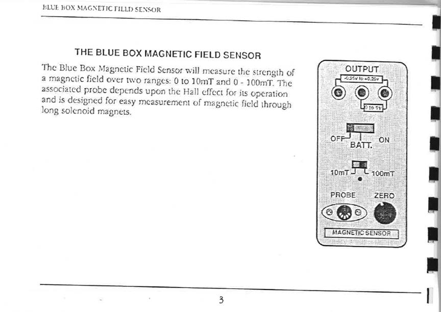
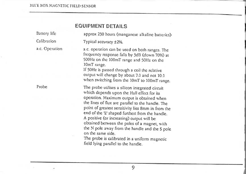
The output of the Philip Harris Magnetic Field Sensor is directly proportional to the strength of the magnetic field at the probe. The Hall sensor is inside the “foot” end of the probe, with the sensor axis oriented perpendicular to the “foot”. The Blue Box output voltage ranges from 0 to +1V. Magnetic fields can be measured on two scales, switch-selected: 10 millitesla and 100 millitesla.
Note on units of magnetic field The System-International (SI, commonly known as the MKS system) unit of magnetic field strength is the tesla (T), which is the same as kg/(coulomb second) 1 T = 104 gauss Gauss is used in the cgs (centimeter-gram-second) system of units. The earth’s magnetic field is about ½ gauss. |
|
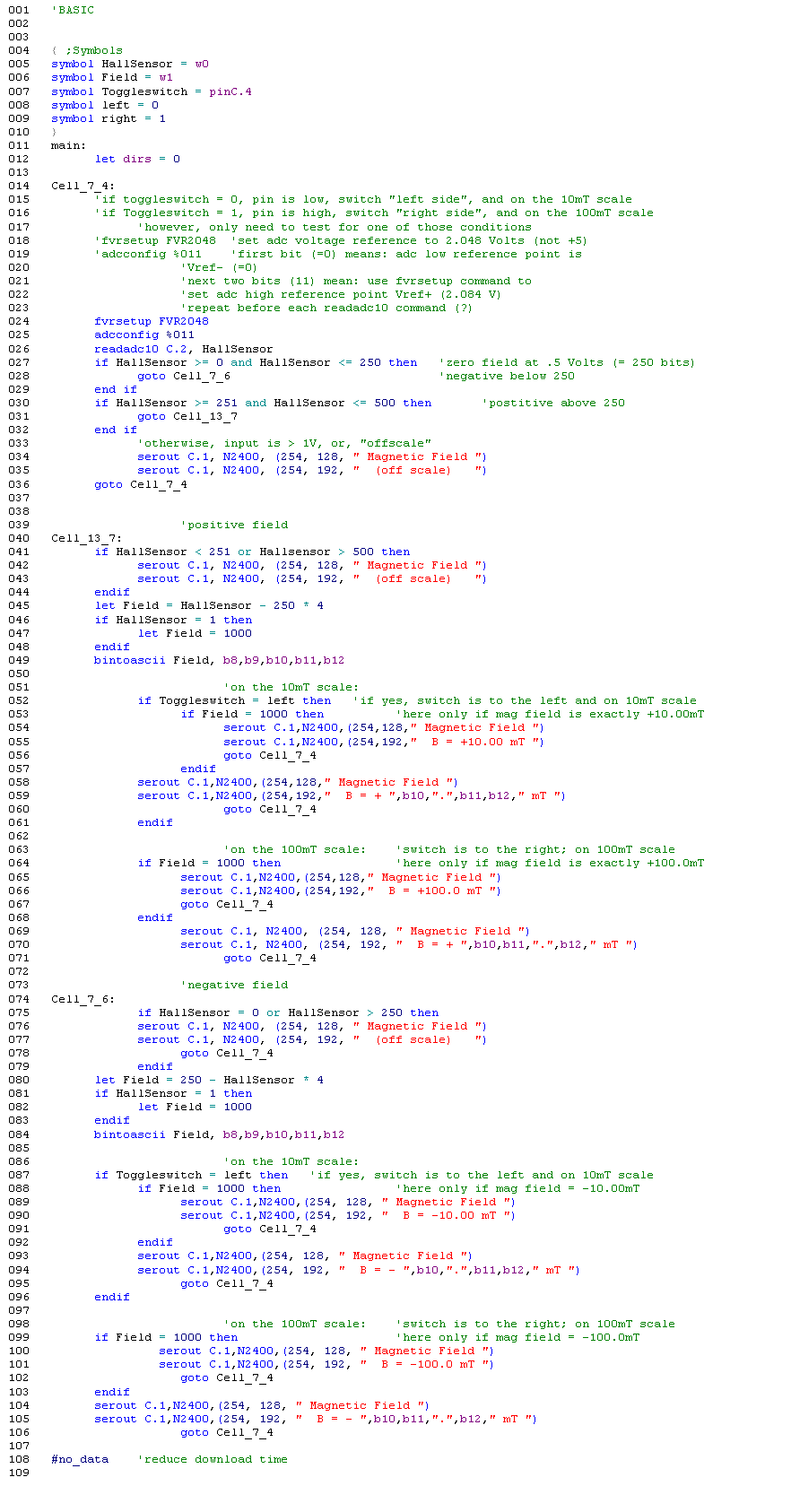
Some PicAcxe Basic Commands First, define some variables such as these: symbol variablename = pinC.2 ‘for example symbol HallSensor = w0 ‘w0 and w1 are word variables, i.e., 16 bit symbol Field = w1 symbol Toggleswitch = pinC.4 ‘defines both variable name and which pin it represents symbol left = ‘either 0 (“low”) or 1 (high) symbol right = ‘either 1 (if left is low) or 0 (if left is high)
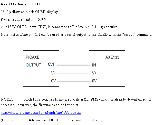
Commands related to reading the analog or digital logic input: fvrsetup FVR2048 adcconfig %011 readadc10 C.2 if variablename = 1 then (etc.) ‘this statement reads the input to check the “if” logic; ‘variablename must be defined with “symbol” statement; ‘”if” query is true when pin is high Commands related to displaying the output: bintoascii serout C.1, N2400_4,(254, 128,” “) serout C.1, N2400_4,(254, 192, “ “,b9,b10,b11,” “) Note that whatever is within the parenthesis is displayed on the OLED. Make sure that there are exactly 16 characters and/or spaces within the parenthesis. 128 is the leftmost position on line 1 of the OLED 192 is the leftmost position of line 2 of the OLED bintoascii converts a bit number to a display character. Commands related to logic and math: if variablename = 0 then . . . endif goto (linename) VariableA = VariableB * 2 + 800 / 7 ‘math protocol strictly from left to right; integers only |
|
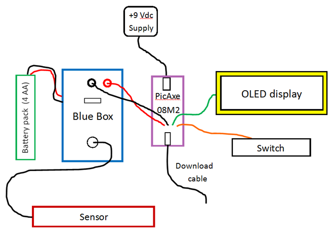
Power Supply on PicAxe Circuit Board Power Input: +7.0 V to +35.0V; connector is center positive; nominally +9.0V dc power adaptor is used (+9.0 V battery for portable use, but avoid if possible since current drain is high - battery won’t last long). Power Output: +5.0 V, regulated 200mA maximum current Red LED “on” indicator. This power supply is hardwired to both the PicAxe and the OLED display; red lead positive/black lead ground, 0V. |
|
Blue Box Manual |
|
Solution |

|
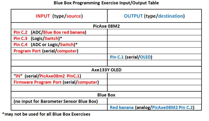
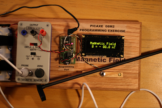
The Assignment The task here is to write a PicAxe program to read the analog input C.2, convert that to magnetic field strength, continuously update and display the result on the OLED. The OLED display must include the term “Magnetic Field” centered on the first line. The second line must display “B = “ followed by the current value written with the proper unit (mT) and some indication, say, a plus or minus sign, of the field orientation, North or South. |
|
Preliminary Tasks The logic of the toggle switch must be determined. NOTE: The Blue Box is separate and independent of the PicAxe microprocessor; thus the switch selection on the Blue Box is not automatically reflected in the microprocessor. The purpose of the toggle switch in front of the OLED is to correlate the scale within the microprocessor program to the Blue Box scale. To display the magnetic field properly on the OLED the toggle switch position must be programmed into the PicAxe and the switch position must match the switch on the Blue Box. The orientation of the magnetic field direction must be determined. The field is measured at the “foot” of the sensor with maximum sensitivity 8mm from the end opposite the sensor handle. With no magnetic field in the region of the sensor, adjust the “zero” control such that the voltage output of the Blue Box is exactly +0.5 V. With that adjustment, an output voltage of zero to +0.5 V indicates one orientation of the field (either North or South pointing “up”) and an output voltage of +0.5 V to +1.0 V indicates the opposite orientation. Use a known magnet to discover the correct orientation. |
|
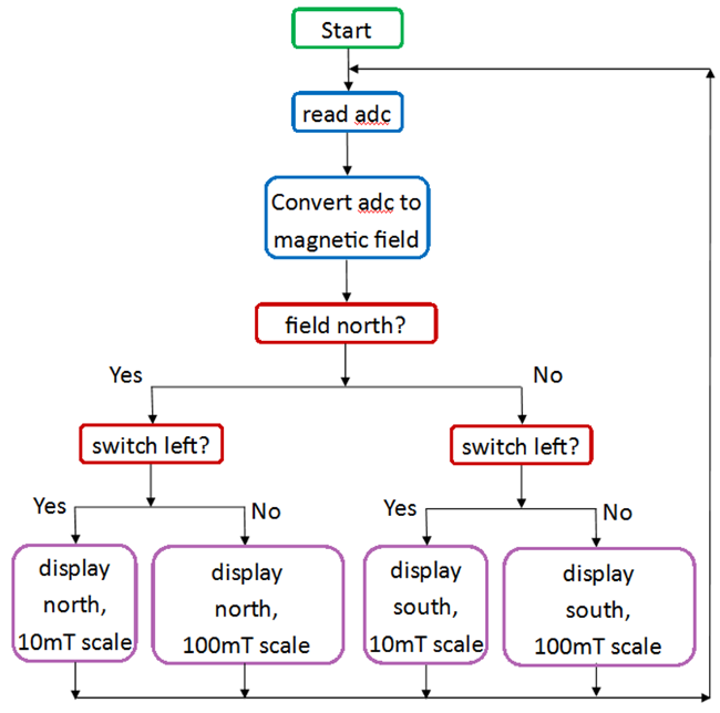
The Solution The simplest solution is to write a Flowchart in Logicator first, then convert the Flowchart into Basic language. Inevitably, the Flowchart will not be complete so a modification of the program will be necessary. Use Programming Editor 6 to complete the program. The Flowchart might look something like this: |

|
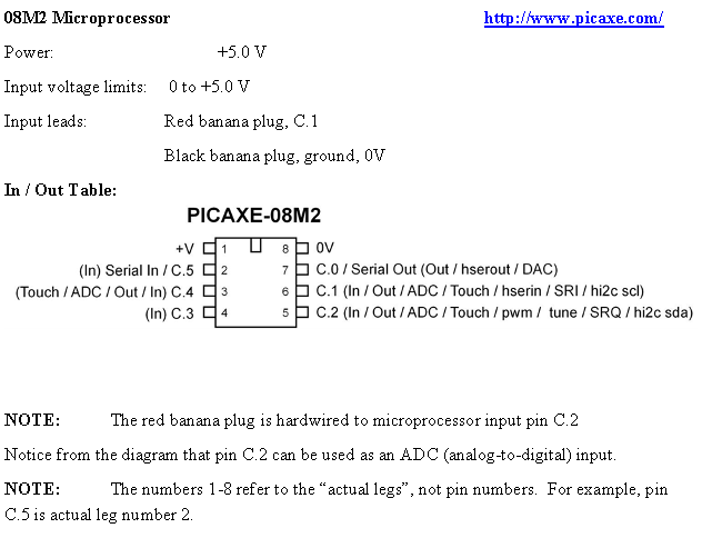
Toggle Switch (in front of the OLED) Two position toggle switch – single pole, double throw. Switch is hardwired to – and switch logic is read at – Picaxe microprocessor pin C.4 Black lead connected to ground, 0V / White lead hardwired to PicAxe microprocessor pin C.4 To find the logic of the switch, use a voltmeter on the microprocessor actual leg of pin C.4 (check the diagram above, and be careful not to short other actual legs). Zero volts means logic state “low”, or 0; +5.0 V means logic state “high”, or 1. |
|
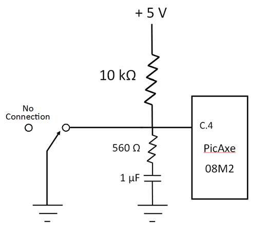
Switch circuit diagram: |
|
Switch circuit analysis: If the switch is in the position as shown, pin C.4 is shorted to ground and is thus low. In the other position, no connection, the pin C.4 is connected to +5.0 V through the 10 kΩ resistor. In this case the pin is high (at +5.0 V) because a) no d. c. current flows through the capacitor, and b) the microprocessor input impedance is quite high; therefore it draws no current through the 10 kΩ resistor and thus there is no voltage drop across the 10 kΩ resistor – making the voltage at the pin equal to +5.0 V. The 560 Ω resistor and the 1μF capacitor act as a filter to “debounce” the switch. Mechanical switches often make-and-break several times when the toggle is thrown only once. This filter prevents the voltage at the pin from fluctuating and driving the microprocessor crazy when this situation occurs. |
|
Philip Harris Magnetic Field Sensor Blue Box
Use only the red and black banana jack connectors on the Blue Box. Never use the blue banana jack.
Power requirements: +6.0 V; separate external battery pack Battery pack red lead positive/Black lead ground, 0V
Output (red/black banana jacks): Output ranges from 0 Volts to +1 Volt, and is linear in magnetic field strength sensed by the probe. Red jack, voltage out; Black jack, ground, 0V.
Field orientation and zero field: With no magnetic field in the region of the sensor, adjust the “zero” control such that the voltage output of the Blue Box is exactly +0.5 V. With that adjustment, an output voltage of zero to +0.5 V indicates one orientation of the field (either North or South pointing “up”) and an output voltage of +0.5 V to +1.0 V indicates the opposite orientation. Use a known magnet to discover the correct orientation.
Switch in “BATT” position: The Blue Box output will be +1.0 V if the battery voltage is +6.0 V. Replace batteries if this output is below +0.75 V (corresponding to a battery voltage of +4.5 V).
Two scales, switch selected, correspond to a maximum magnitude of magnetic field of 10 milliTesla and 100milliTesla.
NOTE: The Blue Box scale switch selection must match the toggle switch selection for the output to display the field correctly on the OLED. NOTE: Do not use blue banana jack – negative voltage on the PicaAxe input may damage the microprocessor. |
|
|


|
|
Switch Left |
Switch Right |
|
Logic state of pin C.4 (high or low) |
|
|