|
Copper Wire Resistance |


|
EOS |
|
Physics |
|
Measuring the Resistance of a Length of Thin Copper Wire |
|
The idea is to find the resistance per meter, Rper meter, of a length of thin copper wire. Once this is known, the length of a wire wound into a coil can be found if the coil resistance, Rcoil, is measured. This length is given, then, by
Lcoil = Rcoil/Rper meter |
|
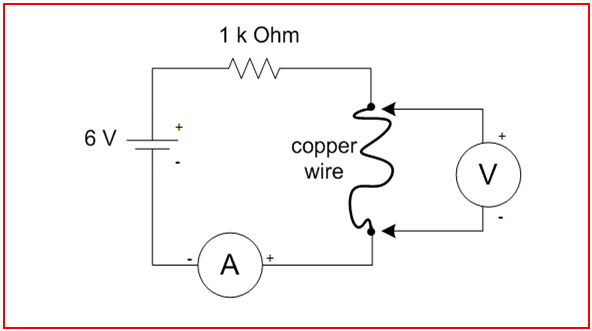
Circuit
The 1 kΩ series resistor limits the current from the 6 V dry cell and this current may be estimated using Dr. Ohm’s Law. Since the copper wire, the ammeter, and the hook-up wires all have small resistances compared to the 1 kΩ resistor, and since the battery is nominally 6 Volts, the current is approximately i = 6V/1 kΩ = 6 mA.
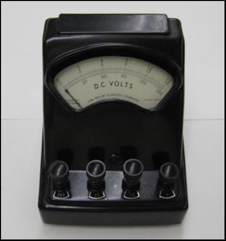
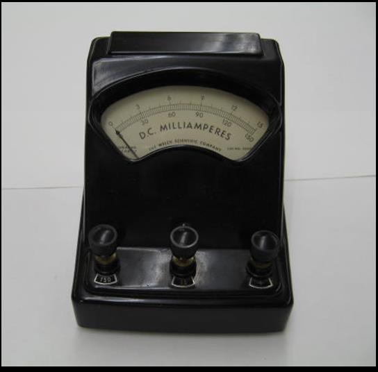
“A” in the diagram refers to an ammeter; “V” refers to a voltmeter. The typical old-fashioned analog ammeters still found, sometimes, in freshman laboratories will peg the meter the wrong way if hooked up in the wrong orientation, so pay attention to the signs; the plus sign refers to the red terminal on the meter. Now that you have an approximation of the amount of current in the circuit, be very careful not to overdrive the meter — that is, use the proper scale. The delicate dial indicator is of the d’Arsonval type, and is easy to burn out, or, perhaps damage the internal spring with too much current.
The ammeters found in the lab are not calibrated—at least, not since they were manufactured (if then). But we may as well carry on as though they were. We could make a stab at calibration, but what would we calibrate them against? We might use the value of the 1kΩ resistor and measure the voltage across it, but the voltmeter is not calibrated, either; furthermore, the 1 kΩ resistor in use here is specified by the manufacturer to be only within 1%. The point here is that any instruments in the lab which we might use for calibration are not any more well-calibrated than the ammeters themselves.
The ammeter will have a small screw on the face below the dial. This adjustment is used to set the zero level on the meter when there is no current through the meter. |
|
Schematic Diagram |
|
Analysis
Experiment
The resistance of this piece of copper wire is given by
R = V/i.
= 0.0111 V / 5.82 x 10⁻³ A
= 1.91 Ω
The resistance per unit length is
Rper meter = R/L
= 1.91 Ω / 2.155 m
= 0.885 Ω/m
Theory
Now, calculate the wire’s resistance using the resistivity of copper so you can compare it your measured result to see whether you are on the right track. The resistance is given by
Rcalculated = ρCu L / A
where A is the cross-sectional area of the copper wire,
A = 1/4 π D2.
Divide both sides by L to find the resistance per meter
Rcalculated per meter = Rcalculated / L
= 4 ρCu / π D2
= 0.834 Ω/m
The value of resistance per meter calculated from the measured voltage and current is about 6% higher than the value calculated from the resistivity of copper. With well-calibrated instruments, the uncertainty in electrical measurements could be less than 1%. |
|
Data
The wire is a single strand of #34 American Wire Gauge (AWG) enameled copper.
Record at least three significant figures in your measured data, if the meters allow. Use MKS units throughout.
i = 5.82 mA = 5.82 x 10⁻³ A current through the copper wire, as measured with the ammeter.
V = 11.1 mV = .0111 V measured voltage across the copper wire.
L = 2.155 m length of the copper wire, measured at the points of the electrical connections.
Look these up in a trustworthy reference source such as the CRC Handbook of Physics and Chemistry:
D = 1.6002x10⁻⁴ m diameter of the 34 gauge copper wire.
ρCu = 1.678x10⁻⁸ Ω m resistivity of copper at 20° C; a property of the material.
|


|
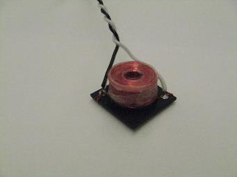
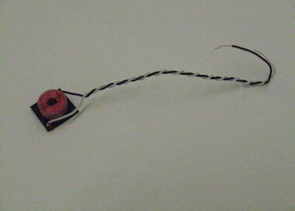
Length of Coil
The length of the wire in the coil now can be calculated. Let’s use the experimental value of resistance per meter. If the coil of this gauge wire has a resistance of 56.0 Ω, then the length of the wire is
Lcoil = Rcoil/Rper meter
= 56.0 Ω / 0.885 Ω/m
= 63.3 m
= 208 feet.
|
|
Not all voltmeters measure differential voltage. The “voltage probe” type of meter which is used with digital electronic data collection systems may tie one lead, typically the black lead, to ground. If so, this may disrupt your circuit unless you are measuring a voltage with respect to the ground set by the data collection system.
To avoid this problem, a d’Arsonval type of volt meter, or, perhaps a battery powered multi-meter, may be used here, but again, the scale and the orientation of the leads must be correct, and we will ignore any calibration errors. If the positive terminal of the meter is connected as shown in the diagram, the meter will read a positive number.
|